Optional LP Designation: What it really means for your next cabling project?
There is a lot of buzz surrounding the optional LP designation for communications cabling right now, and it’s easy to get confused. What does the LP designation actually mean? What’s required versus recommended by the NEC? Do you need to install LP designated cabling on your next project?
There are very some important things to consider before deciding whether or not to install LP designated cabling for your next project. This article will discuss why the LP designation came about, the testing performed to set the various LP designations, what is required versus recommended by the NEC, and, finally, how to determine if your project does in fact require LP cabling.
How and why the Limited Power (LP) designation came about
Prior to the beginning of the review cycle of the 2017 National Electrical Code (NEC), there was some concern regarding temperature rise in large bundles of 23 AWG or 24 AWG twisted-pair data communications cables due to heat produced while carrying low voltage direct current (DC). The NEC generally focuses on higher voltage, larger AWG cables used in construction projects, in order to minimize the risk of electric shock and fire. The requirements for communications systems and associated cabling are governed exclusively by Chapter 8 within the NEC. Currently, the NEC is worded in such a way that it permits up to 100 watts “per circuit” to be carried over communications cables. Each pair in a four (4) pair data communications cable could be considered a “circuit;” thereby technically allowing up to 400 watts of power over communications cables. Combine this with the fact that the IEEE is now developing 802.3bt, which is the 3rd generation of Power over Ethernet (PoE) http://www.berktek.us/eservice/US-en_US/navigate_329396/Power_over_Ethernet.html> and will allow more than 3X the power levels that the second generation of PoE allowed (30W to now almost 100W) through communications cabling. The trend is clear; powering more devices using communications cabling is coming. The question becomes: What are the limitations from heat generation due to power deployment, especially in large cable bundles?To address these concerns, an effort was undertaken by Underwriters Laboratories (UL) to define a new cable marking of Limited Power (-LP) for communications cable. The LP cable designation indicates that the cable has been evaluated by UL to carry the marked current in any reasonable worst-case installation without exceeding the temperature rating of the cable.
LP testing methodology
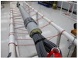
LP testing is significantly different from the applications testing performed to measure a cable’s overall network performance. In LP testing, a homogeneous cable bundle of 192 cables is built and placed in six feet of non-metallic conduit, and each end of the conduit is filled with insulation to minimize air movement (Figure 1). An electric current is then applied to each conductor between 0.5 amps and 1.0 amp, in 0.1 amp increments. For example, if testing for LP 0.5, then 0.5 amps (100 W) is applied to each conductor in the 192-cable bundle. A temperature probe is placed in the middle of the bundle and on the jacket of the center-most cable to take the worst-case temperature reading after maximum sustained temperature is reached. There are six (6) LP markings for data communications cabling (see Table 1). Language taken directly from the draft UL 444 7.24.2, and 7.24.3 is below for reference as well. Please note that the cable bundle is homogeneous. The LP marking does not take into consideration the circumstance where some cables are LP listed and others are not, and the others may have lower temperature ratings and smaller AWG sizes.
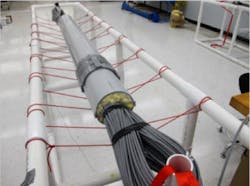
Figure 1: LP Testing
Per the June 2016 draft of UL 444 7.24.2, LP cabling is tested as such:
“The cables shall be arranged in a bundle consisting of 192 cables and electrically connected in series to a power supply capable of providing the rated current marked as part of the LP rating. The inner 37 cables shall be arranged in a hexagonal densest packing structure which represents the worst case thermal dissipation situation. The remaining cables shall be evenly distributed in a random fashion to form a 192-cable bundle. The bundle shall be placed in a 1.83 m ± 5 cm (6 foot ± 2 in) long commercially available non-metallic conduit (Schedule 40) with the minimum diameter needed to install the bundle without putting pressure on the cables. Each end of the conduit shall be filled with insulation.”
Per the June 2016 draft of UL 444, 7.24.3, Limited Power (LP) cabling is measured as such:
“The temperatures shall be measured on the outer jacket and conductor insulation of the center cable at the midpoint of the cable. In addition, temperatures shall be measured on the jacket and conductor insulation on the center cable 0.6 m (2 ft) on each side of center thermocouple.”
The optional LP marking requirements and what they mean
The requirements for the optional LP markings are based on three (3) criteria. They are:
- The cables maximum rated temperature listing (e.g., 60°C, 75°C, or 90°C)
- The amount of electric direct current applied to each conductor (0.5 amps to 1.0 amps in 0.1 amp increments)
- The temperature rise in the center of a 192-cable bundle associated with the electric current applied.
The three requirements lead to this equation:
Temperature rise from electric current applied
+ 45°C (assumed maximum ambient temperature of operating environment)
≤ Cable’s maximum rated temperature listing
An example: Cable under test had 0.5 amps per conductor applied (100 W assuming 50 volts). The temperature rise at the center of the bundle was determined to be 20°C. The cables maximum rated temperature listing is 75°C. Therefore, the calculation would be: 20°C + 45°C ≤ 75°C. Since 65°C < 75°C, the cable meets the requirement for LP 0.5. The cable could then be tested for LP 0.6 by increasing the current to 0.6 amps per conductor and after maximum sustained temperature rise is attained, repeat the calculation. Please see Table 1 for the six (6) optional LP markings for communications cabling.
Why are there so many levels of the optional LP marked cable?
The original intent was to define a single LP listed cable listing that would allow the maximum 400 W deployment on communications cabling. However, it quickly became apparent that such a cable would be cost prohibitive, and may not fit within the connectivity, so multiple ratings were proposed to allow for cost-effective, innovative solutions to be developed. With the exception of LP 0.5 (0.5 amps per conductor or 100 watts), these classifications fall above all current and proposed maximum power deployment systems.
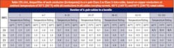
How to read Table 725.144 that is in the draft NEC (2017) Article 725 and referenced by Article 840?
The table in the Article 725 of the 2017 NEC is derived from a UL fact-finding study conducted in 2015 and applies to four-pair, class 2 and class 3 power-limited circuits that transmit power and data to a powered device, regardless if the cable has the optional UL LP marking or not. For example, the chart illustrates that in a homogeneous bundle of 192 cables, it would be considered allowable to transmit up to 0.5 amps through each conductor (100W) of a 75°C listed cable constructed with 23 AWG conductors. UL conducted the testing and based their results with an assumed 45°C maximum ambient temperature. The NEC, however, uses 30°C as their maximum ambient temperature. Therefore the UL marking, which based qualification upon a 45°C ambient temperature is more stringent for a given current due to having 15°C less temperature budget.
Please see Note 1 at the bottom of the chart, which states, “For bundle sizes over 192 cables, or for conductor sizes smaller than 26 AWG, ampacities shall be permitted to be determined by qualified personnel under engineering supervision.”
Note 1: For bundle sizes over 192 cables, or for conductor sizes smaller than 26 AWG, ampacities shall be permitted to be determined by qualified personnel under engineering supervision.
Note 2: Where only half of the conductors in each cable are carrying current, the values in the table shall be permitted to be increased by a factor of 1.4.
Informational Note: The conductor sizes in data cables in widespread use are typically 22-26 AWG.
Products that can safely support 100W
The engineers at the TEK Center at Berk-Tek www.tekcenter.us> have already thoroughly tested and certified that the following products are capable of supporting 100 watts of power safely. This is the maximum amount of power that the PoE standard (IEEE 802.3bt) currently under development will allow. The products* are:- LANmarkTM-XTP and LANmarkTM-10G FTP
- LANmarkTM-10G2
- LANmarkTM-2000
- LANmarkTM-1000
- LANmarkTM-6
*All products listed are capable of safely supporting >192 cable bundle @ 100 W of PoE. Call 1-800-BERK-TEK for more information.
UL and the National Electrical Code (NEC)
UL released a Certification Requirements Decision (CRD) containing their interpretation of the requirements for listed communications cables to carry the optional LP marking based upon a fact-finding study they conducted in 2015. This CRD represents only the view of UL and is not part of any ANSI standard. Concurrently, UL has initiated a proposed revision to UL 444, the standard for communications cable and is seeking industry comment on the LP cable certification requirements.
The NFPA is in the process of completing the 2017 revision of NFPA 70, commonly known as the National Electrical Code (NEC) and is expected to publish the next edition in August 2017.
There are no current or proposed requirements to require LP marked cables to be installed. Article 840 (Premises-powered Broadband Communications Systems) in the forthcoming 2017 edition of the NEC states that power distribution at or below 60 watts does not require any special consideration. However, for power levels above 60W, Article 840 references Article 725 which provides guidance on limiting current and bundle size (although the NEC never defines “bundle”) through proper conductor size (AWG) (See Table 725.144 located on page 4 of this document). Please note that the optional LP Designation is not in Article 800 which governs Communication Circuits (LAN cabling and Connectivity).
There are no current or proposed plans to require LP marking within the NEC. It is intended to be an optional marking. A significant amount of opposition still exists from many different industry organizations, including IEEE, Ethernet Alliance, BICSI, and others. Additional industry studies are needed to generate a more specific set of operational parameters and requirements for LP marking to achieve industry consensus. Additionally, immediate adoption of the latest version of the NEC is not mandatory and varies by individual states.
What the LP designation doesn’t consider
The purpose of any NEC safety listing, is to make the installation and operation of electrical circuits as safe as possible. So while Berk-Tek understands the intent of the LP designation, we do not believe that this optional designation actually makes anything safer. Here are five (5) points that support our position:
- LP designation is optional. It is not a requirement under the NEC, nor is it expected to become one. True safety measures are required listings, not optional designations.
- The LP designation does not consider the entire channel. The cable itself is the only part of a solution that can be LP-designated. Other important components, such as connectors, patch cords and patch panels, are not considered.
- The LP designation is only for homogeneous bundles. The testing and markings for LP cables came about from one very-specific test set-up, which does not mirror real-life installations such as trays, J-hooks, or mixed cable bundles.
- The burden of safety is on the user, not the system. There are no fail-safe mechanisms, such as circuit breakers or fuses, to shut down the current if needed, as there are in traditional power channels.
- The NEC allows qualified engineers, such as those at The TEK Center at Berk-Tek, to certify the maximum current and bundle size, regardless of the optional LP designation.
What about the data?
LP is an optional designation appended to a safety listing, but another important consideration, which LP does not take into account, is the effect that heat rise will have on your data.
To illustrate the performance difference with various types of cabling, Berk-Tek developed the Converged Application Score (or CA Score). The CA Score is an indicator of how well IP traffic is protected and how much temperature rise there is when the cable undergoes PoE testing. The score is represented by a numeric value between 1 and 10, with 1 being the worst and 10 being the best (see Figure 2). A higher score means that there were fewer flaws noticed in our application testing of VoIP, Data, and IP Video. Also, a higher score indicates that the cable experienced less heat rise while supplying 100 W of power in a large bundle. More information on Berk-Tek’s CA Score can be found here www.berktek.us/everythingip>.
Figure 2: CA Score graphic illustrating different levels of performance
About Berk-Tek
For more than 50 years, Berk-Tek has been a leading manufacturer of more than 100 different network copper and fiber optic cable products. The company has led in the development of high-performance and enhanced fiber optic and UTP cables designed to transport high-speed data and voice transmissions. Berk-Tek has manufacturing facilities at New Holland, PA, and Fuquay-Varina, NC. For more information, visit www.berktek.com.

