Sandia updates its intrabuilding cabling
Acknowledging the limitations imposed by old wiring systems, the project team designed the cabling infrastructure to satisfy Sandia`s current requirements and industry cabling standards.
Roger Adams
Sandia National Laboratories
Timothy Francis
Holmes and Narver Inc.
Sandia National Laboratories teams with federal facilities, industries and universities in technology development across a broad spectrum of engineering disciplines. The Laboratories recognized that applying innovative telecommunications technologies was essential to meet the information exchange demands of collaborative research and development efforts. Management committed to using asynchronous transfer mode (ATM) switching and synchronous optical network (Sonet) technologies as the core of Sandia`s internal networking strategy. Sandia initiated the intrabuilding recabling project (IRP) with a team that became responsible for upgrading the New Mexico campus` antiquated telecommunications cabling infrastructure to support all of Sandia`s communications (voice, video and data) networks.
In the past, costly iterations of cabling were required to accommodate vendor-specific schemes. This was a major reason for the Laboratories` recabling commitment. Sandia-specific structured cabling system standards were considered essential to meet the requirements of its networking strategy. From the beginning, the project team intended that these new standards would be implemented in all new construction projects as well as in ongoing moves, adds and changes within Sandia`s campus.
At a minimum, this new infrastructure had to comply with current national and international telecommunications standards and meet the needs of Sandia`s R&D community. In addition, it had to satisfy Sandia management`s cost-containment expectations. An aggressive schedule targeted the complete recabling of nine buildings and support for construction of four new buildings by September 30, 1995. To meet this schedule, the recabling team installed approximately 7500 telecommunications outlets in these 13 buildings, bringing new telecommunications connectivity to 60% of Sandia`s New Mexico population. In 1996, five existing buildings are also scheduled for recabling.
The IRP team faced many challenges with the project, including
Acquiring, storing, controlling and distributing large inventories of material
Accomplishing construction work in an occupied building
Assembling and managing huge contracting crews to meet aggressive construction schedules
Addressing Environmental Safety and Health issues, primarily asbestos abatement
Distilling a final design from the many available options
Prioritizing buildings to receive new cabling.
Sandia`s enterprise connectivity and how it is achieved by its evolving high-speed network is determined by the design concepts, standards and the installed configuration of its intrabuilding recabling project. This includes cabling components such as multimedia outlets, the horizontal distribution system and intermediate distribution rooms.
Design considerations
Because of the unique nature of the R&D activities conducted at Sandia National Laboratories, special design considerations and standards were adopted for the campus cabling. The computing bandwidth requirements of thousands of users at Sandia`s New Mexico facility range from downloading simple text documents from local servers to distributed processing via multiple Cray supercomputers and Paragon parallel processor computers.
One critical design concern that the IRP team had to face was physical and electronic information security. Inside Sandia`s secured area, some buildings require secure (red) and open restricted (black) access capabilities. To satisfy this requirement, two identical (but physically separate) distribution systems were installed--one red and one black. Buildings outside the secured area require only black, open restricted access capabilities.
The concepts behind the recabling project under which the IRP technical staff worked included creating a standards-based, structured cabling system that provided the following:
The capabilities to satisfy telecommunications requirements within Sandia`s corporate information architecture
Physical protection for the cabling system. The design had to address all present and anticipated security requirements as mandated by the U.S. Department of Energy
An interface with existing hardware configurations, to the greatest extent possible, which would enable the preservation of previous networking hardware investments, primarily legacy local area network hardware and desktop personal computers and workstations
Flexibility and scalability to meet the present and anticipated demands of a premier R&D facility
Advanced communications channel capabilities. Careful performance and installation consideration had to be given to every cabling component to create integrated end-to-end communications channels that were predictable and reliable.
Sandia`s IRP cabling infrastructure design established standards and specifications for user outlets, cabling, horizontal distribution systems, intermediate distribution rooms and interconnecting components. These design standards--the foundation of the overall cabling infrastructure design--incorporated current national and international telecommunications standards modified for Sandia-specific requirements such as security and enhanced bandwidth. As an essential step in delivering a uniform telecommunications cabling infrastructure, these standards are being deployed in all new building construction and any major building renovations.
To move away from vendor-specific designs, the team incorporated telecommunications standards that had matured over the last decade. Existing industry standards were referenced in areas of telecommunications service entrances; equipment rooms; telecommunications closets; building backbone systems; grounding, bonding and electrical protection; horizontal cabling systems; firestopping; and cable administration.
Cabling standards
Because no site-specific design guidelines were available, communications engineers based their solutions on their knowledge of Sandia`s mission, current networking configurations, security requirements, state-of-the-art networks and current telecommunications standards. The cabling standard includes enhanced unshielded twisted-pair copper cables and multimode and singlemode optical fiber as transmission media. Each outlet contains three enhanced UTP 4-pair cables, one multimode 4-fiber cable and one singlemode 4-fiber cable.
All of the cables are terminated in one surface-mounted multimedia outlet. The outlets are either red or black, visually corresponding to the secure or the open restricted access cabling system. Construction teams mounted multimedia outlets in every office to achieve true desktop connectivity. In addition, multimedia outlets were mounted in laboratories, computer rooms, secure vaults and conference rooms.
Sandia`s cable configurations exceed the national and international standards in two ways:
Quantity of conductors.
Current national and international standards recommend a minimum of two circuits per outlet. Sandia`s multimedia outlet permits seven circuits per outlet. This assumes that two fibers will be dedicated for one optical circuit and two pairs of each 4-pair enhanced UTP cable will be dedicated to one electrical circuit. This is an extremely conservative deployment of circuits. The development of wavelength-division and bidirectional optical technologies and eventual use of all pairs within 4-pair enhanced UTP cables means that many more circuits will be available within each outlet.
Conductor types.
Sandia`s multimedia outlet includes enhanced UTP copper conductors that exceed current Underwriters Laboratories` Category 5 UTP certification. The outlet also includes singlemode optical fibers, which provide more bandwidth capability than recommended by national and international standards.
In addition to the horizontal cabling, some indoor high-conductor-count optical-fiber and UTP cables were installed as part of the intrabuilding cabling project. Indoor optical fiber and UTP cables connect intermediate distribution rooms with telephone building-entrance protector frames. Outdoor optical-fiber and UTP cables connect intrabuilding cabling to interbuilding cabling by linking main IDRs to technical control centers. These control centers are geographically distributed and connected with singlemode optical-fiber cables, forming the high-speed campus backbone.
Horizontal distribution
Sandia`s original building wiring often used daisy-chained wall-mounted metallic enclosures to house horizontal crossconnects. Over the years, the number of crossconnect enclosures proliferated, and the wiring inside became increasingly scrambled and unmanageable. The old wiring, punchdown blocks, horizontal crossconnects, intermediate distribution frames and telephone building-entrance protector frames, and the lack of centralized, environmentally controlled equipment rooms, rendered the interconnectivity of Sandia`s network unreliable. Moves, adds and changes were a challenge facing the technicians, especially when the cabling was not labeled or documented.
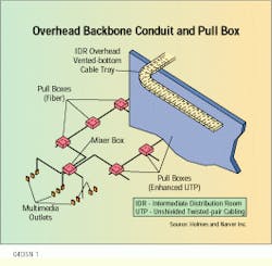
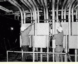
The intrabuilding recabling project requires that all cabling from the user outlet be routed directly back to an intermediate distribution room, according to the EIA/TIA-568 standard. This horizontal distribution eliminates crossconnect points, but requires the installation of many conduit and pull boxes.
All cables are routed in conduit from the intermediate distribution room to the multimedia outlets with no splices or crossconnects. Because of security requirements and stringent fire codes at Sandia, conduit was selected for cable pathways. Optical-fiber and enhanced UTP cables are routed in separate conduits from the IDR through several pull boxes. From a final pull box, smaller conduit connects to a "mixer" box where optical fiber and enhanced UTP cables are combined. From the mixer box, the cables are routed in conduits sized to support single or back-to-back multimedia outlet configurations. The final mixer box provides connectivity for nine multimedia outlets. All conduit fills allow for a minimum 10% additional capacity to accommodate future needs.
The centralized destinations for all conduit and cabling within a building are the intermediate distribution rooms. The main ones connect to individual ones within a building and to telephone building-entrance protector frames, as well as to multimedia outlets. Main intermediate distribution rooms are also connected to technical control centers external to the building and are located according to the 90-meter distance required by the EIA/TIA-568 standard. Depending on building layout and design, the number of IDRs in each building varies from one to four and ranges in size from 225 to 600 square feet.
The conduit, equipment racks, copper termination frames, cable tray and optical-fiber interconnect panels require a considerable amount of space in each building--space relinquished begrudgingly by building occupants. One of the most difficult challenges for the project team--technically and politically--was finding, retaining and retrofitting appropriate space for the intermediate distribution room.
Efficient use of space
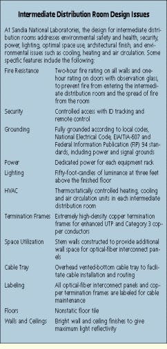
Because of the space issue, the design required efficient use of floor and wall space. Optical-fiber interconnect panels consumed the most wall-space area within the intermediate distribution room. For example, in a room with 398 panels, 9552 fiber-optic connectors are terminated in the panels. Eight-foot stem walls were built to increase total wall area and, in extreme cases, optical-fiber interconnect panels were stacked in columns seven panels high. (The manufacturer recommends stacking as high as six columns.) This wall configuration occupies 30% less floor space and also allows wall space for future growth.
Intermediate distribution rooms provide a centralized point for all telecommunications maintenance within the building, including moves, adds and changes. In addition, these rooms usually house equipment racks, active telecommunications electronics, uninterruptible power supplies, termination frames and any other equipment required for enterprise-wide connectivity. Some examples of active telecommunications electronics are:
Local area network hubs and concentrators
Routers and bridges
ATM switches and edge devices
Video distribution and conferencing equipment
Statistical, frequency and time- and wavelength-division multiplexers.
Enterprise connectivity
With the new cabling infrastructure in place, Sandia`s enterprise network can proceed toward its long-range goal: achieving ubiquitous data transmission to the desktop at gigabit rates, using Sonet technology as the physical transport and ATM technology for electronic switching. This network will allow quick deployment of ATM standardized bit rates (anticipated to include 25, 51, 155 and 622 megabits per second) to the desktop.
Connectivity to the desktop and optical-fiber cable connectivity between the intermediate distribution rooms and technical control centers complete the link between the end user and the enterprise network. The centers are interconnected with a singlemode optical-fiber cable backbone providing campus-wide connectivity. As the campus grows, new intermediate distribution rooms and technical control centers will be introduced into the topology. Sandia`s combined intrabuilding recabling, enterprise networking and ATM migration projects will provide virtually unlimited bandwidth and connectivity throughout Sandia`s evolving high-speed network, including links to distributed databases and centralized supercomputers.
The success of the recabling project, which was based on extensive planning and up-front design, is essential to the effective management of Sandia`s telecommunications needs. The cabling infrastructure within each building is the foundation upon which all present and future telecommunication strategies at Sandia National Laboratories are, or will be, built.
The 28.6-square-mile New Mexico campus of Sandia National Laboratories comprises its headquarters and laboratories.
The horizontal backbone distribution design uses conduit from the intermediate distribution room to the multimedia outlets with no splices or crossconnects.
Pull boxes and conduit replace the need for crossconnect points in the intermediate distribution room.
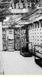
A typical intermediate distribution room at Sandia approaches completion.
Roger Adams, Registered Communications Distribution Designer (RCDD), is a member of the technical staff at Sandia National Laboratories, and Timothy Francis, RCDD, is senior telecommunications specialist at Holmes and Narver Inc., both in Albuquerque, NM.
