Designing a structured cabling system for voice and data

While meeting performance requirements for voice alone is relatively easy, the new heterogeneous communications environments are more challenging.
Richard Perron
Northern Telecom
The design of wiring systems for voice communications has not changed radically over the last twenty years. Bringing a telephone line to a user`s desk is a simple and well-understood task. However, changes in business applications require the integration of voice applications with support for data, graphics, integrated services digital network connections, and other services over a single, standardized cabling system. We are beginning to see the beginnings of this new age of unified multimedia in the telecommunications industry. For example, asynchronous transfer mode is knocking at the door--promising to combine voice, high-speed data, video and imaging applications in one high-performance network infrastructure.
In contrast to voice systems, data communications cabling systems have undergone many changes during this same period. Data network cabling has evolved from the proprietary solutions of the 1970s, with shielded twisted-pair and coaxial cabling, to the rise of standards-compliant structured wiring systems in the late 1980s, when unshielded twisted-pair, or UTP, and optical-fiber cable predominated. In addition, data communications is no longer confined to a particular department or even a single company. The exchange of information is essentially without boundaries.
Planning is key
Managing and designing separate systems to support voice and data will become a thing of the past. System designers now have to plan telecommunications infrastructures without knowing whether any given user will require two voice ports, such as phone and fax, with one data port or only one voice and two data ports, such as Ethernet and video. The need for this kind of flexibility means that proper planning for present and future applications is essential. All new structured cabling designs and installations should conform to a high-performance cabling standard, as defined in the Category 5 specifications of the Telecommunications Industry Association/Electronic Industries Association-568-A standard for commercial building telecommunications. End-to-end Category 5 systems can deliver the services that users need today and for the future. Some important issues that you should consider when designing and installing a system for present and future needs include the following:
Standards that regulate the telecommunications industry and performance requirements
Design and installation specifications for the telecommunications infrastructure
Testing options to ensure maximum system performance.
Before getting started
In the late 1980s, EIA/TIA cabling and related standards were developed to provide guidelines for designers, installers, end users and manufacturers. Before that time, electrical and building codes were used; but their main concerns were safety and construction. Four major standards were developed to address proper infrastructure planning and the overall performance of the cabling system, as follows:
TIA/EIA-568-A (formerly EIA/TIA-568, first issued in July 1991), commercial building telecommunications cabling standard. This standard addresses the telecommunications wiring system requirements for commercial buildings that support various local area network, data, voice and image/video systems. Canadian Standards Association T529 is the equivalent standard.
EIA/TIA-569, commercial building standard for telecommunications pathways and spaces. This standard defines the design and construction practices within and between buildings (primarily commercial establishments) that contain telecommunications media and equipment. CSA T530 is the Canadian standard equivalent.
TIA/EIA-606, design guidelines for administration of telecommunications infrastructure in commercial buildings. CSA T528 is the Canadian standard equivalent.
TIA/EIA-607, commercial building grounding and bonding requirements for telecommunications. CSA T527 is the Canadian standard equivalent.
You should also be aware that standards bodies occasionally release specific telecommunications systems bulletins in addition to the published standards.
Since the main concern of standards is to provide users with guidelines that allow them to prepare and implement a telecommunications system that is as flexible and durable as possible, performance criteria for subsystems are at the heart of standards development. These criteria are specifically addressed in the TIA/EIA-568-A standard, which deals with twisted-pair and optical-fiber cable specifications.
Some of the most crucial planning decisions involve horizontal distribution, where changes may be difficult to make once the installation is complete. The selection of media must therefore be carefully analyzed. Today, the medium of choice for horizontal distribution is unshielded twisted-pair cable.
Copper as the horizontal medium
To deliver a high level of system performance, you should use a controlled or approved communications medium that takes into account such transmission characteristics as attenuation, near-end crosstalk and structural return loss. Performance criteria for copper twisted-pair cables are defined as follows:
Attenuation is the loss of signal strength measured in decibels. It is a function of the length of the cable; that is, the longer the cable, the more the signal is attenuated.
Near-end crosstalk is the crossover of electrical energy between adjacent pairs of wire in the same cable. A higher value is better.
Structural return loss is a measure of the uniformity of characteristic impedance over the length of the transmission path. A high value of structural return loss in decibels reflects a uniform cable impedance.
Capacitance, resistance and other specifications are also important as they directly influence the performance criteria mentioned above.
Specifications such as these are crucial in determining the ability of a wiring system to deliver reliable transmission. Indeed, the industry has further classified performance abilities into categories of wiring components that help users select the proper product for the application, whether it is voice, data, video, or a combination thereof.
The following categories are currently used:
Category 3 applies to 100-ohm UTP cable and associated connecting hardware whose transmission characteristics are specified to 16 MHz.
Category 4 applies to 100-ohm UTP cable and associated connecting hardware whose transmission characteristics are specified to 20 MHz.
Category 5 applies to 100-ohm UTP cable and associated connecting hardware whose transmission characteristics are specified to 100 MHz.
Note: Levels 1 and 2 cable (specified prior to Category 3) and connecting hardware are not recognized as part of the standards and should not be used in horizontal cabling systems.
Discussions about using optical-fiber cable connections to the desktop are prevalent in the telecommunications industry. Some applications, in fact, may require the use of optical fiber either immediately or in the near future. But most installations today do not have such requirements. Although the cost of optical-fiber cable has come down, opto-electronic devices are still expensive enough to make copper the selection of choice for horizontal distribution.
Designing and installing the cabling plant
After you determine applicable standards and make media choices, it`s time to look at an end-to-end Category 5 system design and installation. To simplify the process, first define the subsystems of the telecommunications infrastructure. For each subsystem, consider a few basic design rules and installation recommendations that allow you to maintain performance and achieve long-term serviceability. The industry has developed a cable structure with distinct elements such as the work area and telecommunications outlet, horizontal cabling, telecommunications closet, horizontal crossconnect and backbone cabling.
Work area
Work area components extend from the telecommunications outlet/connector end of the horizontal cabling system to the station equipment. They typically include modular line cords and telecommunications outlets.
Using a modular line cord, attach each workstation network interface card to the telecommunications outlet. The distance should not exceed 3 meters in length (TIA/EIA-568-A, proposed CSA T529).
Modular line cords consist of 24 American Wire Gauge, or AWG, insulated solid conductors. The cords must not degrade the required channel performance characteristics of the system. This is usually one of the most frequent causes of failure in an installation. For example, cords made from Category 5 horizontal cable will likely fail at some point in time because they typically cannot withstand the average 600 pounds-per-square-inch pressure generated by the plug termination.
The telecommunications outlet is the interface between the horizontal wiring and the modular line cord connecting the terminal. The eight-position modular UTP telecommunications outlet and its pin assignments should meet the requirements of the EIA/TIA-568-A standard. Label each outlet on the cover plate with its unique designation.
Horizontal cabling
The horizontal distribution cabling links the crossconnect system to the communication outlets in the work areas. Typically, horizontal cabling is installed in a star configuration.
Run a minimum of two, four-pair Category 5 cables to each work area. Provide dedicated four-pair UTP horizontal cable for each application planned. Terminate each four-pair cable on an eight-position modular connector at the telecommunications outlet. Provide additional telecommunications closets on large floor areas of a building to limit the horizontal distribution to 90 meters (295 feet), which is the distance recommended in the standards.
In addition to the crossconnect hardware, telecommunications closets can house such communications equipment as controllers, multiplexers, bridges, routers, and LAN hubs in cabinets or on racks.
The closets should be equipped with a minimum of two duplex 110-volt AC power outlets with grounded receptacles and separately fused at 15 amperes (for North American standard installations). Climate control should be provided in the closet seven days a week, 24 hours a day to extend the life of the electronic components and for all mission-critical applications.
Size the copper crossconnect system appropriately to support the telecommunications outlets served by that closet. In the layout, allow for anticipated growth. Make all terminations on insulation displacement contact, or IDC, crossconnect or patch-panel systems. Terminate and test all the horizontal and backbone copper and fiber-optic cables, regardless of the method of termination.
Use patch cords within each interconnect or crossconnect. You can also use crossconnect wire for IDC crossconnections, but neither of these cables should exceed seven meters in length, according to TIA/EIA-568-A.
Backbone cabling
Backbone cabling extends from the main crossconnect to each of the horizontal crossconnects as well as any intermediate crossconnects between buildings in a campus installation. Designers determine the type of media--copper or optical-fiber cable--to use in backbone cabling based on the application and the distance requirements. Backbone cabling is typically installed, with separate dedicated cables to each horizontal crossconnect and intermediate crossconnect.
Proper grounding and bonding is essential. Refer to the appropriate codes and standards; for example TIA/EIA-607 (CSA T527). Use 6 AWG copper to ground the metal shields. Backbone systems must also comply with applicable national, regional or local building and electrical codes.
Intrabuilding cabling
The intrabuilding backbone provides the connection between the main crossconnect (or, in a campus, the intermediate crossconnect) within the building, and the horizontal crossconnect in the telecommunications closets that it serves. When using Category 5 UTP multipair cable in the backbone, the number of copper cables dedicated to each floor should be sufficient to accommodate all the horizontal circuits served by the backbone cable--recommended minimum is two pairs per circuit--plus 25% spare for growth.
Where the distance capability of copper is inadequate, use multimode (or singlemode, where applicable) fiber in the backbone. Install a minimum of twelve optical fibers for each horizontal crossconnect to ensure support for new services and provide redundancy.
Place backbone cabling through shafts, conduits, raceways or floor penetrations, and always provide support for the cable according to the manufacturer`s design guidelines. Vertically align telecommunications closets wherever practical. If this is not possible, conduit may be required to link the telecommunications closets with the backbone cable.
The interbuilding backbone provides connection between the main crossconnect and all the intermediate crossconnects in other buildings that it serves. Use cables rated for the required outdoor use, for example, aerial, buried or conduit. It is recommended that all copper cable pairs between buildings be protected at both ends by surge protection devices.
The main crossconnect, or intermediate crossconnect, is the common point of connection for copper and optical-fiber backbone cabling, the private branch exchange, computers, and interbuilding cables, as well as connections to telephone-company interfaces. It provides a single administration point for the entire building/campus telecommunications network. Because of the large number of cable terminations usually required at the main crossconnect, IDC connection hardware is typically used.
Testing an installed system
Once you have completed the design and the system has been installed, verify that the cabling has been installed correctly. For a copper or optical-fiber cabling installation, you need to perform a certain number of required tests, using various techniques and measuring devices.
For a well-designed installation with a proper performance assurance program, a simple continuity/wire mapping evaluation may be sufficient. However, more in-depth testing can be performed if necessary; for example, testing for signal attenuation, near-end crosstalk and noise. Time-domain reflectometer measurement tests are also useful for troubleshooting.
Because near-end crosstalk measurements can be different at opposite ends of a cable, it is recommended that you measure the near-end crosstalk from both ends of a cable. If the measurements differ, always consider the worst-case values for analysis.
By adhering to the appropriate standards, design and installation requirements, and testing procedures, you can build a structured wiring system that is ready to support your customer`s present and future needs. Cable is not "just cable"; it is a critical component for successful business communications. When your cabling system is designed and installed properly, it can deliver a high level of performance. That level of performance will ensure that the infrastructure you build today will be able to support the applications of the future, including asynchronous transfer mode and multimedia networking. This maximizes the useful lifespan of the wiring infrastructure, significantly increasing its value as a long-term investment.
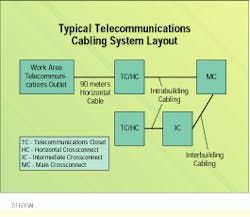
The industry has subdivided the telecommunications cable system structure into distinct elements.
Proper Termination is Essential
Installers should follow some basic guidelines when terminating Category 5 cables; for example, do not untwist pairs more than approximately 13 millimeters (0.5 inch). This applies to any individual pair within the end-to-end link, including terminations at patch panels and outlets. The maximum cable jacket removal length, however, can vary from 25 mm (1 inch) to approximately 400 mm (14 inches), depending on the type of product on which the termination is performed.
Also, when dressing unjacketed twisted pairs, prevent any excessive bending of the cable. Minimum bend radius for a copper twisted-pair cable is approximately 5 mm (0.2 inch), which is approximately four times the pair diameter. Secure the cable with cable ties, but do not overtighten the ties on the jacket; maintaining cable geometry maximizes system performance. Also remember that the maximum pulling tension for four-pair 24 American Wire Gauge horizontal cables should not exceed 25 pounds to avoid stretching the conductors during installation.
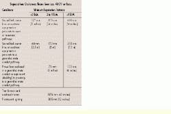
You should also follow the recommendations for minimum separation distances to ensure adequate protection of the unshielded twisted-pair cable from electromagnetic interference sources. For power greater than 480 volts and power ratings greater than 5 kilovolt-amperes, apply engineering calculations to determine the exact electromagnetic interference separation distances.
Richard Perron, Eng., is a registered communications distribution designer, local area networks, and a technical support specialist at Northern Telecom IBDN, St. Laurent, Quebec.

