Enhanced-performance Category 5--A look at usable bandwidth
The enhanced-performance cables now being offered by some manufacturers call for understanding many more electrical properties than has been the case with lower-grade cable.
Eric Lawrence,
Berk-Tek
As networking demands escalate, new data-communications applications will call for higher and higher transmission rates. A perfect example of this is the development of Ethernet. The original Ethernet standard over twisted-pair wire operates at 10 megabits per second, so it is known as 10Base-T. Fast Ethernet operates at 100 Mbits/sec, and now the 802.3z Working Group of the Institute of Electrical and Electronics Engineers (ieee--Piscataway, NJ) is developing 1000Base-T, or Gigabit Ethernet, which will operate at 1000 Mbits/sec. In order to run these increasing data rates over standard Category 5 cable, application developers are forced to be increasingly efficient at using the available bandwidth of the copper medium.
When Category 5 cables were first introduced, efficiency was not a primary concern, since the data rates of existing network applications were only a fraction of the available bandwidth of the cable. In fact, only two of the four wire pairs were used, the other two pairs in the 4-pair cable being kept as spares.
Of the two pairs that were used, signals were transmitted over one and the other was employed to receive signals. This transmission scheme is commonly known as half-duplex operation. Since two pairs are needed to both send and receive a signal, the effective bandwidth of the pairs is halved.
Category 5 cable was developed to have a bandwidth of 100 megahertz. The cable is swept-frequency tested up to this level by its manufacturer, and it has adequate signal-to-noise ratio to operate even at the maximum frequency of 100 MHz. Signal-to-noise ratio is quantified by measuring attenuation-to-crosstalk ratio (acr). However, since the maximum length of a horizontal cable run was established by standard at 100 meters, attenuation was not considered to be a bottleneck for bandwidth and the focus has instead been on crosstalk, specifically near-end crosstalk (next).
Another consideration that is important in characterizing cabling systems is electromagnetic interference (emi). The burden of meeting regulations of the Federal Communications Commission (fcc--Washington, DC) and similar electromagnetic compatibility (emc) standards has been placed primarily on the active equipment manufacturers, since compliance is determined on an individual basis and cannot be predicted for all instances of a particular network application. However, emi results not only from active equipment but also from the network infrastructure and the interaction between active and passive components.
With half-duplex operation, the 100-MHz bandwidth of a Category 5, 4-pair, unshielded twisted-pair (utp) cable is effectively split between the transmitting and receiving pairs. At 50 MHz per pair over the two pairs, the total usable bandwidth of the cable in half-duplex operation is 100 MHz. For applications such as 10Base-T, which operates at 10 Mbits/sec, the efficiency of this type of use of Category 5 cable is not high--only 1 Mbit/sec for every 10 MHz of usable bandwidth. Even over Category 3 cable, the ratio of Mbits/sec-to-MHz only approaches unity. However, as data rates in the network escalate, this ratio also increases. For 155-Mbit/sec Asynchronous Transfer Mode (atm), for example, the protocol has to pack more than 1.5 Mbits/sec into each megahertz of bandwidth for Category 5 cable.
A way of looking at how efficiently bandwidth is being used is to compute the ratio of Mbits/sec-to-MHz. This ratio can be used to estimate the maximum data rate that can be supported for any given bandwidth. For example, if the total usable bandwidth of a medium is 100 MHz and the ratio of Mbits/sec-to-MHz is 5:1, then the maximum data rate that can be supported will be approximately 500 Mbits/sec.
This ratio is dependent on many factors, including the encoding scheme used. This scheme, in turn, partially determines the complexity and cost of the transceivers needed to send and receive data. The relationship between complexity and efficiency is not necessarily linear. For instance, to double the Mbits/sec-to-MHz ratio, which allows the data rate to double using the same bandwidth, the cost of the electronics may increase tenfold because of added complexity. The practical limit to bandwidth efficiency is a function of cost as well as the current state of the technology; therefore, it is an ever-moving target.
More bandwidth from enhanced cables
One way to reduce the cost of applications requiring very complex and costly electronics is to increase the amount of usable bandwidth in the cabling medium, so that less complex electronics are needed. By increasing the usable bandwidth, the ratio of Mbits/sec-to-MHz is reduced, which can in turn reduce significantly the cost of transceivers.
There are several ways to increase usable bandwidth in a cable:
- Use all four pairs in 4-pair cable. If all four pairs are used instead of only two, then the usable bandwidth can be doubled. If the 100-MHz bandwidth of Category 5 cable is available over two pairs, then using the other two pairs in 4-pair cable in a similar manner doubles the usable bandwidth to 200 MHz. However, there are extra performance requirements that must be met to ensure proper operation under these conditions. For instance, power-sum specifications must be applied to the cable to characterize the additional interactions between multiple transceivers.
- Transmit and receive using the same pair. Half-duplex operation uses separate wire pairs to transmit and receive. This transmission method effectively halves the potential bandwidth of each pair, assuming that it is possible to use the same pair to both transmit and receive signals. The latter type of transmission, known as full-duplex operation, calls for the data traffic on a pair to travel in both directions. By using all four pairs, the total usable bandwidth of a Category 5 cable may be as high as 400 MHz--100 MHz per pair for each of four pairs. To achieve this level of operation, how-ever, the cable must meet performance specifications beyond what is currently included in wiring standards such as ansi/tia/eia-568a of the Telecommunications Industry Association (tia--Arlington, VA) and iso/iec 11801 of the International Organization for Standardization and International Electrotechnical Commission (iso/iec--Geneva, Switzerland).
- Increase the usable bandwidth of each pair. The delivery of more than 100 MHz of bandwidth per pair permits the total usable bandwidth of 4-pair cable to be scaled up proportionally, regardless of how many pairs are actually used or whether the transmission is full- or half-duplex. For example, if all four pairs are used in full-duplex mode, the total usable bandwidth of 4-pair Category 5 cable is 400 MHz. If each pair can transmit 150 MHz, though, then the cable`s total usable bandwidth is increased to 600 MHz.
Enhanced-performance Category 5 cable, now offered by a number of different cable manufacturers, is designed to have electrical performance characteristics that allow the cable to support applications requiring bandwidth beyond the 100-MHz Category 5 ceiling, making it possible to simplify the electronics and reduce the cost of the network. This can be a cost-effective strategy, since the additional cost of cabling is usually much less than that of more-complex electronics. Also, the cable plant now has additional bandwidth to support future applications, so the network manager can increase the data rate of the network by changing the electronics and not the cable plant.
A case in point illustrating this strategy can be found in 100-Mbit/sec Fast Ethernet. There are several infrastructure choices available to the network manager today that will carry this protocol. Category 3 utp cable can be used, for instance, if a bandwidth-efficient encoding scheme is applied. This is the method used for 100vg-Anylan.
Category 5 cable calls for a simpler encoding scheme, which is less bandwidth-efficient but also calls for simpler and less costly electronics. This is the technique used for 100Base-Tx. Of the two networking solutions, the Category 5 cabling is lower-cost and has the advantage of offering sufficient spare bandwidth to permit upgrades in the future as higher-data-rate applications such as 1000Base-T come online. It is for these reasons that 100Base-Tx is much more common than 100vg-Anylan when the cabling must be installed.
The same logic can be applied to enhanced-performance Category 5 cable. Although 1000Base-T, for instance, will be supported by standard Category 5 cable, enhanced-performance Category 5, if properly manufactured and specified, will offer more usable bandwidth and will therefore be better able to handle higher-data-rate applications and provide some insurance that the network manager will have spare bandwidth to support forthcoming applications using the existing cable plant.
Higher performance over enhanced cable
The trend toward increasing the usable bandwidth of Category 5 cable is not new. Cabling-industry standards committees have been working for some time on a specification to support bidirectional traffic over all four pairs. This standard revision will increase the usable bandwidth of Category 5 cable from 100 to 400 MHz.
Additional performance specifications, as noted earlier, should be considered if the end-user wants to be assured of supporting full-duplex transmission over all four pairs in 4-pair cable. These specifications are needed so that applications can make full use of Category 5 and enhanced-performance Category 5 cables. They are also necessary for shared-sheath operation, where more than one network application is run on the same cable using different wire pairs, as well as in cases where the application is not symmetrical. As a result, specifications for such cable parameters as power-sum near-end crosstalk (ps-next) are now being considered as additions to the Category 5 wiring standard.
Shared-sheath applications, especially, call for careful consideration because ps-next measurements being used to characterize enhanced-performance cables do not take into account all the factors affecting performance in this environment--for example, far-end crosstalk (fext--interfering signals from transmitters operating at the far end of the link) and possible differences in voltage levels between applications also can influence shared-sheath performance. To combat such problems, several Berk-Tek product lines offer a minimum of 6 decibels of ps-next margin over the backbone requirements in the tia/eia-568a commercial building telecommunications wiring standard, as well as proposed horizontal cabling requirements for Category 5 cable being considered for future standard revisions. The 6-dB margin is sufficient to permit up to a 2:1 ratio between voltage levels of differing applications sharing bandwidth in the same sheath, the 6-dB margin being the decibel equivalent of a 2:1 voltage ratio.
An example of Category 5 applications operating in a shared sheath and having a 2:1 voltage difference between them is 100Base-Tx running with 155-Mbit/sec atm. The 6-dB cross-talk margin over the value specified in the Category 5 standard must be measured using a power-sum technique, since multiple disturbers exist simultaneously in the cable.
Specifying ps-next may not completely ensure the proper operation of enhanced-performance cable operating at high bandwidth, but it is nevertheless an important consideration. Multipair transmission relies on cable carrying several transmitting pairs, all of which are operating near the receiver. next from each of these potentially disturbing wire pairs must be added together to determine the crosstalk seen at the receiver.
The separate power, measured in watts, of the crosstalk generated by these pairs is added together and the total power converted back into decibels to give a composite crosstalk signal called power-sum near-end crosstalk. It should be clear that, to support bidirectional operation, ps-next must be specified from both ends of the cable, since transmitters operate alternately at each end of the link.
To adequately support bidirectional traffic, the cable must take into account fext as well as disturbances at the near end. fext is usually smaller in magnitude than next because of attenuation over the length of cable. The composite sum of all far-end crosstalk signals is known as ps-fext, or power-sum far-end crosstalk.
The ps-fext measurement is useful in several ways. It can be added to the ps-next measurement to determine the total interfering signal a receiver sees from all transmitters, near-end and far-end. ps-fext is also normalized with attenuation and called el-fext, or equal-level far-end crosstalk. This parameter is used along with the acr measurement to evaluate the cable`s signal-to-noise ratio.
Attenuation-to-crosstalk ratio has become a familiar term in the Category 5 marketplace. It is specified for links in the international wiring standard, iso/iec-11801, and it has been introduced as a cable parameter in Berk-Tek and other enhanced-performance Category 5 cables. acr is important because it provides accurate information on how well a cable can use its specified bandwidth.
Simply specifying acr, however, does not guarantee that complex applications will be accommodated by the cable. For this reason, Berk-Tek has defined what it believes is a more comprehensive acr measurement, specifying the attenuation to power-sum crosstalk ratio, abbreviated ps-acr, of its enhanced-performance cables. acr alone is a sufficient measurement for applications that use half-duplex operation and run on only two pairs, but for more advanced protocols, the crosstalk signal that is measured must include the interference from all disturbers on the cable and not just from one.
Although an adequate ps-acr margin is much more difficult for manufacturers to achieve, it is necessary to ensure proper shared-sheath operation and should be part of the information provided to systems integrators and network managers by vendors wishing to fully characterize their cabling products.
Enhanced cables need improved balance
Twisted pairs in a cable use a differential transmission scheme to reduce radiated emissions and lessen susceptibility to noise. In this scheme, the two insulated conductors of a twisted-wire pair are balanced with respect to ground, meaning that each conductor has the same impedance between itself and ground. This is a very different transmission scheme from that found on an unbalanced transmission line such as coaxial cable. In the latter case, the two conductors in the cable are not balanced with respect to ground and have different impedances. In fact, the outer conductor in a coaxial transmission system is often tied to ground.
Differential transmission involves splitting in half the signal to be transmitted and sending one-half down one insulated conductor of the twisted pair and the other half of the signal, phase-shifted by 180o, down the other conductor. The 180o phase shift inverts the signal--in other words, a +1V signal becomes a -1V signal. The receiver at the far end of the cable subtracts the two signals, restoring the original signal. This technique explains the name, "differential transmission."
The advantage of differential transmission is that any external noise coupling onto the wire pair will be canceled at the receiver, as long as the noise signal is the same on both insulated conductors of the pair. At the same time, any signal radiating from one conductor of the pair will add to the opposite signal radiated from the other conductor, with the two radiating signals canceling each other since they are opposite in polarity. This reduces noise on the cable that can interfere with the transfer of data, and it limits a cable`s emission of emi into the surrounding environment.
Differential transmission assumes that each insulated conductor is similar enough to the other conductor in the pair for full cancellation to occur. In reality, physical and electrical differences between the conductors in wire pairs cause imbalances that practically limit the noise that can effectively be canceled. The actual electrical balance of the pair, then, can play a significant role in the ability of the cable to meet radiated-emission and noise-susceptibility requirements. Balance also plays an important role in controlling next and affecting other performance parameters. Poor balance in a wire pair, for instance, can foster unwanted common-mode signals coming from the transmitter, which can result from limited output signal balance (osb) in the active electronics.
Lack of balance in cable can cause differential signals to convert to common-mode signals as a result of differences in attenuation, time delay, and impedance between the two insulated conductors of the twisted pair. Since the receiver has a finite common-mode rejection ratio (cmrr), it may not be able to completely subtract the two signals coming from the transmitter, and a portion of the common-mode signal will remain.
Well-balanced wire pairs are necessary, then, to ensure proper operation of transmitters and receivers, to control emi of the system, and to prevent crosstalk or attenuation beyond the limits placed on these parameters.
Although screening or shielding Category 5 cable with a foil shield can be an effective way to reduce emi both radiating from and coupling onto the cable, this technique should be thought of as an additional safeguard above and beyond the noise cancellation of balance, and not as a substitute for it. This is because common-mode signals can transfer from unbalanced cable to the electronics, due to limitations on cmrr and osb. Thus, noise can radiate from the electronics despite any shielding added to the cable. Therefore, to properly perform as part of a system, twisted-pair cable must be well-balanced regardless of the presence of shielding.
Testing balance
With the need for balanced cable established, it is necessary to review how Category 5 products can be adequately balanced. Although under review at this time, the Category 5 cable standard does not currently contain adequate specifications for balance. Also, since balance is by definition a measure of the difference between each conductor and ground, a different problem arises with utp cable in that grounding has not been a recognized issue.
Common-mode signals must have a return path, also known as a ground path. In an unshielded cable, the effective ground can differ depending on where and how the cable is installed. Thus, when the cable is installed in metallic conduit the grounding will vary from when it is installed in plastic conduit. Since the grounding varies, the resultant balance of the cable in each case may also be different. In a component specification, the problem is readily solved by defining the ground plane; this is done by either placing the cable in water or suspending it in the air and performing a measurement. This practice is sufficient to give system designers a start, but they also need to carefully consider changes that may be caused by differing installation practices.
There are several tests that can be performed to measure the balance of a wire pair. The International Telecommunication Union--Telecommunication (itu-t), formerly known as ccitt, has in its recommendation G.117 several measurement methods that may be used for different purposes. This document is referenced by iso/iec-11801 and other industry wiring standards.
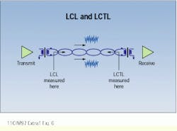
Two methods are referenced in iso/iec-11801. The first is longitudinal conversion loss (lcl), which is sometimes also called longitudinal balance. This property is measured by applying a common-mode signal to the cable and measuring the differential signal at the same end of the cable. This differential signal is caused by mode conversion in the cable that results from its finite balance. The method is similar to an impedance measurement, since the same end of the wire pair is used to both inject the test signal and measure the result.
The second measurement of pair balance is longitudinal conversion transfer loss (lctl). lctl is similar to lcl, in that a common-mode signal is applied to the cable pair and the resultant differential signal is measured. The difference between the two measurements is that, with lctl, the differential signal is measured at the opposite end of the cable into which the common-mode signal was injected.
Attenuation or signal loss
The attenuation of a twisted pair, measured as insertion loss, is a familiar concept in specifying Category 5 cable. Insertion loss is a measure of the loss a signal experiences as it propagates down the pair. The power that is lost results from several factors. Some of the signal is converted to heat due to the resistance of the copper wires or the slight conductivity of the insulation material. A portion of the energy is also reflected as the signal encounters impedance changes through the length of the cable. In addition, energy can be lost as radiation because of common-mode conversion and subsequent coupling to free space. All of these losses, as well as others, are collectively measured as insertion loss and specified for Category 5 and enhanced-performance Category 5 cables so that system designers can calculate the level of signal that will reach the receiver.
Since different loss mechanisms can affect some transmission frequencies more than others, it is important that attenuation be measured across the entire bandwidth of the cable. Two hundred samples per frequency decade are usually sufficient for this purpose; this equates to about 400 data points between 1 and 100 MHz. For any given transmitter power and cabling length, the lower the signal attenuation, the better.
Low attenuation is especially important when bandwidth is increased beyond 100 MHz. In such a case, the cable may be attenuation-limited, meaning that there is insufficient signal left at the receiver for network applications to function even though acr and ps-acr are within established limits.
Sampling an adequate number of frequencies across the cable`s bandwidth is important for evaluating many electrical parameters besides attenuation. For example, to reduce signal levels at specific frequencies to meet fcc and other system emc regulations, digital signal processing techniques are being used today to scramble the signal. This has the effect of spreading the signal energy over a wide band of frequencies, so parameters such as attenuation, impedance, crosstalk, acr, and balance must be tested across the entire bandwidth of the cable and not just at a handful of discrete frequencies to accommodate this technique.
Impedance uniformity
As applications such as analog video over utp cable become more commonplace, employing as they do broadband analog signals over a wide range of frequencies, it is necessary to use cable with consistent electrical performance. Two of the best measures of the consistency of a cable`s construction throughout its length are impedance uniformity and structural return loss, both of which are needed to fully characterize the performance of the cable.
Measuring impedance uniformity provides a good idea of the consistency of the cable`s construction, since tight impedance control above 100 MHz is an excellent indicator of uniformity. But it is not sufficient to characterize performance because the information supplied is in the form of magnitude only. An enhanced-performance Category 5 cable should meet the requirements laid out in the stringent iso/iec-11801 testing method. These requirements include measuring structural return loss (srl), which is the deviation of impedance from a nominal value. srl is calculated using both the magnitude and phase of the input impedance, so the information provided is more complete than the impedance measurement alone.
As a new generation of networking applications springs up, the standards of the cabling industry for the copper twisted-pair cabling medium are changing as well. To meet the demands for full-duplex operation and multipair, bidirectional transmission, which will be necessary to support the high bit rates of these new applications, enhanced-performance Category 5 cables must be designed, specified, and constructed to comply with forthcoming standards that specify such electrical parameters as ps-next, el-fext, and pair balance specified as both lcl and lctl. In addition, the cable of the future needs to support higher-bandwidth implementations that may rely on less expensive electronics. This is accomplished by controlling ps-acr, minimizing attenuation loss, and developing superior impedance uniformity and pair balance up to and beyond 100 MHz. Only by addressing these issues can cable manufacturers meet the needs of the copper cabling plant of tomorrow.
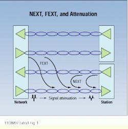
Near-end crosstalk (NEXT) on a wire pair is signal coupled from a nearby pair. It is distinguished from far-end crosstalk (FEXT) by its origin at the near rather than the far end of the cable. Attenuation is the gradual weakening of the signal over distance.
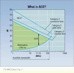
Attenuation-to-crosstalk ratio (ACR) is a measure of the signal-to-noise ratio of a cable. As shown, Category 5 near-end crosstalk limits for cable, connectors, and the channel decline as frequency increases. Attenuation, however, increases with frequency, so the acr declines from about 58 decibels at 1 megahertz to about 4 dB at 100 MHz. The available bandwidth in this example is a little more than 100 MHz, ending where the near-end crosstalk and attenuation lines intersect unless limited by electromagnetic interference or other considerations.
Return loss is the power of all reflected waves measured at the input port relative to transmitter power. It is important because it can lead to attenuation roughness at higher frequencies, reduce acr and increase jitter for digital signals, and cause ghosting in analog video signals.
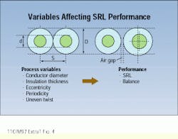
Structural return loss (SRL) is a special case of return loss in which the far-end termination is set to the nominal characteristic impedance of the cable. It is affected by manufacturing variables such as conductor diameter, insulation thickness, eccentricity, and uneven pair twist.
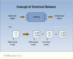
Balance depends on differential transmission in which two equal signals of opposite polarity are transmitted down the conductors of a wire pair. When a common-mode signal is introduced into the wire pair, it unbalances the transmission.
Longitudinal conversion loss (LCL) is a measure of signal unbalance at the transmitter output that results from differential-to-common mode conversion in the cable. Longitudinal conversion transfer loss (LCTL) is a measure of signal unbalance at the receiver input due to conversion from common-to-differential mode in the cable.
Eric Lawrence, registered communications distribution designer (rcdd), is manager of design and development engineering at Berk-Tek (New Holland, PA).
