Extended-frequency testing of Category 5 components and systems
John A. Siemon and Valerie A. Smith
The Siemon Co.
Now that Category 5 cabling is being widely installed for telecommunications applications, some cable and component manufacturers are publishing performance data on operation at frequencies well beyond those specified by standards. The number of manufacturers providing Category 5 test data beyond 100 megahertz is increasing, and the claims in their product literature are fostering misconceptions about the performance of these products. Let`s shed some light on the fallacies associated with extended-frequency testing of Category 5 cable and components.
Among the questions we should ask are:
-What does extended-frequency testing of Category 5 cables prove?
-Of what significance are frequency limits that extend beyond 100 MHz?
-What performance requirements are components and cabling systems tested to?
-What test methods are used to ensure accurate and repeatable measurements?
The most stringent transmission requirements specified by recently approved cabling standards--American National Standards Institute/Electronic Industries Association/Telecommunications Industry Association-568A and International Standards Organization/ International Electrotechnical Commission IS-11801--are Category 5 performance limits that extend up to 100 megahertz for 100-ohm cabling and components. Neither TIA-568A, IS-11801 nor any other national or international cabling standard provides test methods or performance requirements for 100-ohm cabling or components beyond 100 MHz.
The upper limit of 100 MHz was originally selected for Category 5 cable because it defines the point at which the difference between near-end crosstalk and attenuation is 10 decibels for standard test lengths of 100 meters. This difference, also known as the attenuation-to-crosstalk ratio, is used to determine the bandwidth of the cable or cabling system that is available for signal transmission. For installed cabling systems, an attenuation-to-crosstalk ratio of at least 12 dB is considered acceptable for most applications.
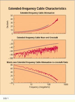
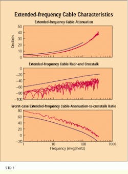
This might lead you to conclude that an extended frequency limit--for example, to 300 MHz--is the point at which the cable delivers an attenuation-to-crosstalk ratio of 10 or 12 dB. However, the extended limits advertised by manufacturers appear to have no relationship to an acceptable attenuation-to-crosstalk ratio. In fact, published attenuation-to-crosstalk ratios for these cables show the 10-dB crossover frequency occurs at 130 to 160 MHz for 100-meter test lengths.
These attenuation-to-crosstalk values reflect margins--typically 5% for attenuation and 6 dB for near-end crosstalk--consistent with those offered by other high-quality Category 5 cables not tested to higher frequencies. They result more from well-controlled manufacturing methods and materials than from proprietary cable constructions, and they do not even approach an acceptable attenuation-to-crosstalk ratio at 300 MHz for 100-meter cable lengths. In fact, the attenuation-to-crosstalk ratio at the upper frequency limit specified by each of the extended-frequency cables is negative for standard test lengths; crosstalk voltage is greater than that of the transmitted signal.
Performance requirements
Given that there are no standard performance requirements for Category 5 cables above 100 MHz and the attenuation-to-crosstalk ratio is clearly not the basis for establishing these new frequency limits, what performance requirements are used to characterize these cables? The performance curves that manufacturers use to convey extended-frequency information are based on equations used to specify Category 5 performance limits as a function of frequency. Manufacturers have simply extended these limits above 100 MHz.
The practice of extending Category 5 performance curves to higher frequencies is a significant departure from the approach taken by standards groups. Standards-based twisted-pair performance specifications not only require testing at higher frequencies for Categories 3, 4 and 5 respectively, but also specify progressively more severe performance thresholds throughout the entire range for each.
For example, if you tested Category 3 cable beyond 16 MHz, the results might imply higher performance than other Category 3 cables. But the data is meaningless unless it proves the product meets standards-based requirements of a higher performance category, such as Category 4, at all specified frequencies.
At this time, neither the TIA nor ISO cabling standards groups are working on performance requirements for 100-ohm cabling or components above those defined for Category 5. There is no assurance, then, these cables would meet the requirements of a higher-performance category if one is introduced.
One significant challenge faced by standards groups is developing test methods that ensure accurate and consistent measurements. A well-defined test methodology allows independent verification of results and alleviates the confusion and frustration resulting from conflicting performance claims. No standard test methods are currently in place for ensuring valid data on components or cabling systems operating above 100 MHz.
Attenuation and crosstalk measurements are necessary to determine the performance capabilities of cabling and components, but they are not sufficient to prove a cable can support a given bandwidth. Other frequency-dependent parameters specified by TIA-568A and IS-11801 include characteristic impedance, structural return loss, nominal phase velocity of propagation (or propagation delay) and longitudinal conversion loss (or balance). Even if attenuation and crosstalk data indicate an acceptable attenuation-to-crosstalk ratio to a given frequency beyond 100 MHz, the cable can only be considered capable of supporting extended bandwidth if the performance of these other parameters is tested and proven in the extended frequency range as well.
Looking beyond components to testing installed cabling, system claims such as "link bandwidth warranted up to 350 MHz" are equally unfounded. Link and channel testing of installed unshielded twisted-pair cabling are still under study by the TIA, and the scope of this work is limited to 100 MHz. Stating a UTP link can be warranted to frequencies above 100 MHz not only implies field-test instrumentation is available that can perform these measurements, but also that nonproprietary test criteria have been defined to ensure applications can be supported beyond 100 MHz.
The truth is there are no field-test instruments that can perform verification measurements on UTP cabling at frequencies above 100 MHz. Even those that perform measurements to 100 MHz have limited accuracy when compared to laboratory-grade equipment used to test cables and connecting hardware. As is the case with cables and connectors, there are no performance standards for testing cabling links beyond 100 MHz. Even if such standards and equipment did exist for these extended-frequency links, the data would only prove this type of cabling is incapable of providing an acceptable attenuation-to-crosstalk ratio to frequencies above 100 MHz.
TIA-568A and IS-11801 state that installed transmission performance shall be classified by the least-performing component in the link. The reason for this requirement is the overall transmission performance of a link can only be as good as that of its worst-performing component. A component with significantly lower performance than others in the link will have a dominant effect in degrading the entire link`s overall performance. For example, a Category 4 telecommunications outlet in the work area will require the link be classified as Category 4, regardless of the performance capabilities of the connecting hardware at the horizontal crossconnect.
This weak-link principle may be carried to cables and connecting hardware that feature performance margins, known as headroom, compared to standard Category 5 limits. These products are also tested beyond 100 MHz. Although additional performance margin in a product is a plus, all other elements in the link must also be of comparable performance to realize the additional margin offered by the higher-performing component. Otherwise, refining performance of components at one end of the link will only serve to shift the worst-case performance to the other end, without achieving either significant gain in the attenuation-to-crosstalk ratio or extended bandwidth capability.
Gains have been made in refining the performance of connecting blocks, but the telecommunications outlet continues to be the weak link in horizontal UTP cabling, with typical headroom of less than 5 dB.
Using high-quality Category 5 cable and connecting hardware that is properly installed, attenuation-to-crosstalk ratio margins of at least 10 dB at 100 MHz are common for links that conform to length requirements. But again, product testing beyond the specified frequency limit has no bearing on the ability of the component or system to provide an acceptable attenuation-to-crosstalk ratio margin above 100 MHz.
One potential benefit that has been claimed for extended-frequency components and systems is they can support extended cable lengths--that is, horizontal cable lengths of greater than 90 meters. This claim is especially appealing for existing structures that cannot serve all work areas with cable runs of 90 meters or less. However, it may also have significant limitations. For example, ensuring users that, based on the attenuation-to-crosstalk ratio, all Category 5 applications will be supported at an extended length fosters the misconception that telecommunications signaling schemes depend on an attenuation-to-crosstalk ratio alone.
When developing applications standards, committees consider such physical-layer issues as squelch levels, equalization requirements, nonlinearity and nonuniformity of cable characteristics, emissions (both radiation and immunity) and jitter buildup in the context of transmitter and receiver design, encoding scheme, termination scheme and other factors. The complex interaction of these variables should be understood before you make any assumptions concerning what tradeoffs are acceptable.
Complex interrelationships
For example, a cable with losses equivalent to 90 meters of Category 3 UTP, but with a length of only 40 meters, might not work properly with 16-megabit-per-second token ring receivers that use adaptive equalization. Although this is just an example of an application that depends on both length and loss, it is well known that the interrelationships of operating parameters defined by an applications standard are extremely complex.
Moreover, the length limits defined by TIA-568A constitute a critical boundary condition used in the development of high-speed applications. As these applications groups continue to push the envelope of signal transmission, the effects of such length-dependent parameters as propagation delay and differential delay on jitter and bit errors may become as important as the attenuation-to-crosstalk ratio. Before making the decision to extend physical lengths beyond what the cabling standards allow, be sure to consult the standards for the applications you expect to run.
Applications requirements
Although applications designed to operate over Category 5 cabling have been pushed to 155 Mbits/sec and beyond, it is important to note that advanced encoding schemes are used to limit their effective signal bandwidth to less than 62.5 MHz. At this frequency, Category 5 cabling requirements provide an attenuation-to-crosstalk ratio of 12 dB, according to Annex E of TIA-568A. Asynchronous transfer mode and other advanced applications designed to operate over UTP are limited to frequencies below 62.5 MHz because it is the recognized attenuation-to-crosstalk ratio cut-off frequency for Category 5 and it satisfies stringent requirements for electromagnetic emissions set by the Federal Communications Commission and other regulatory agencies.
These applications consistently refer to TIA and ISO standards for Category 5 cabling and base their system designs on standards-based cabling system requirements. Because the applications are designed to operate at predefined bit-error rates--typically on the order of 10-10--additional margin provided by extended-frequency components is not necessary to achieve acceptable system performance as defined by the applications standard. There are no standardized signaling applications--either released, pending or under development by ISO, ANSI, the Institute of Electrical and Electronics Engineers or the ATM Forum--that specify UTP cabling components whose requirements exceed those specified for Category 5 cable and connecting hardware.
Published values for attenuation, near-end crosstalk and attenuation-to-crosstalk ratios end at 100 megahertz. By extrapolating the curves beyond 100 MHz, it is possible to make extended-frequency performance claims. The actual measurements for a representative sample of 100-meter lengths of Category 5 extended-frequency cable, versus the extrapolated performance curves, are indicated.
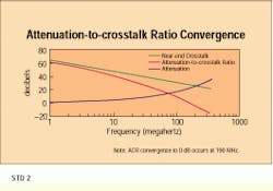
Based on published data for an extended-frequency system, the 12-decibel attenuation-to-crosstalk ratio crossover occurs at approximately 100 megahertz. The crossover to negative ACR values occurs below 200 MHz.
John A. Siemon is vice president for engineering and Valerie A. Smith is an electrical engineer at The Siemon Co., Watertown, CT.


