Multifiber optical connector inspection: The auto-analysis repeatability challenge
It is well accepted that contaminated or damaged optical connectors can bring down networks. Recent technological innovations in optical data transmission methods (specifically PAM4 modulation for 100G single lambda) have reduced optical link budgets, making sensitivity to attenuation and reflection even more pronounced. It has become essential for today’s network operators to engage in 100% connector endface inspection to avoid costly downtime.
Evolution from single fiber cabling to multifiber cabling
With strong consumer and business appetite for even higher broadband speeds, communications technologists, particularly in hyperscale data centers, have exploited every innovation for meeting that demand, including multiwavelength multiplexing per fiber, higher frequency carriers, and parallel optics using multiple lanes of light. This parallelism has driven the popularity of multifiber connectors, primarily MPO/MTP® variants. AFL estimates the worldwide installed base of MPO-type connectors to be north of 10 million endpoints, with north of 1 million endpoints to be commissioned this year alone. Typical MPO cables use a single row of 12 fibers but higher-density alternatives use multiple rows of 12 or 16 fibers. The need to rapidly inspect the endfaces of these connectors has become an operational imperative for both telecom and datacom network managers. A typical hyperscale data center has tens of thousands of MPO connectors to contend with, often by a very small team of network installation and maintenance technicians.
The following cold, hard numbers drive the business need for 100% MPO connector inspection.
- The revenue asset value of a 400G link is about $1M per year (400 customers at 1 Gbit/sec at approximately $100 per month or so, with 2:1 oversubscription).
- About 80% of network failures are related to connector failures, often migrating dirt and other debris driven by aggressive forced-air cooling solutions.
- The average cost of a data center outage is about $740,000, according to Ponemon Institute/Emerson Network Power.
A fast MPO endface inspection tool is essential to help beat back these rising trends, and help large optical network managers sleep at night.
Drivers of next-generation inspection tools
Increasingly, network turnup and maintenance tasks are outsourced to inexperienced technicians, many with limited fiber-handling skills. At the same time, corporate senior managers generally demand their teams to constantly find ways to reduce operating expense. These dynamics conspire to require that network test and inspection tools are simple to learn and use. These tools must also provide easy reporting of results, as a prevailing attitude in this gig economy is grounded in “trust but verify.”
One of the technical innovations in handheld wireless optical connector video microscopes is the use of real-time image processing to automatically analyze endface surface conditions with respect to the severity of scratches and debris contamination. These inspection probes leverage the semiconductor sensors, microprocessors and memories found in modern smartphones. The current generation of fast MPO inspection probes can evaluate pass/fail for each fiber in about 1 second (12-fiber MPO in about 10 seconds), which represents a true breakthrough as compared to older manual mechanical scanning methods, which typically take about 60 seconds per fiber to position and run analysis.
IEC 61300-3-35 (2015) is the most commonly used standard for MPO pass/fail auto-analysis. This standard defines two zones (core and cladding) to analyze for scratches and debris. Pass/fail thresholds for both scratches and defects are established by count and by size (which ranges from 1 to 5 microns—too small to be seen with the naked eye; a micron is a millionth of a meter). This international standard is currently in the process of Edition 3 revision; a new revision is expected later this year or early 2020, with MPO/MTP inspection optimizations. Modern fast MPO inspection probes use both microprocessor and field programmable gate array (FPGA) system-on-chip image processor implementations to algorithmically assess endface conditions.
There are a large number of variables to achieve consistent or repeatable auto-analysis results. Repeatability can be tested by making multiple auto-analysis runs on the exact same connector endface and then studying the pass or fail results fiber by fiber. MPO/MTP endface surface textures and colors vary widely from connector vendor to connector vendor, from quite light and unblemished, to quite dark and mottled. On some MPO endfaces, the fibers protrude 5 to 10 microns from the ferrule surface, creating a tiny dome and a corresponding tiny shadow, making life difficult for a 2D focusing camera and conventional edge-detection algorithms.
Depending on the polish of the connector (flat UPC or 8-degree angled APC), the blue LED illumination level on the endface can vary quite dramatically. MPO/MTP alignment sleeves (sometimes called bulkhead adapters) are precision-manufactured polymer material, but have tolerance limits. The adapter tips on the probes also have mechanical tolerance limits, which stack up with the alignment sleeve and the connector-under-test (patch cord or bulkhead) tolerance. Most importantly, without the use of “artifacts” (expensive ceramic endfaces etched using focused ion beams), there really is no metrological objective standards to use for microscope calibration by the end user. These physical realities limit the precision to which a real-time and low-cost microscope can make consistent and repeatable pass/fail judgments.
Repeatability and consistency of results
It is somewhat intuitive to understand that the auto-analysis repeatability of an absolutely pristine MPO/MTP connector is likely to be highly relative—approaching 100% in most situations. There are simply no scratches or debris detritus to trigger the algorithmic size and count thresholds. The same can be said for filthy or ruggedly used and scratched connectors—there are so many “events” that adjudicating as “fail” is relatively easy. What is interesting and educational to think about are “marginal condition” fiber ends, in which the size and count of the events (scratches and debris) in Zone A (core) and Zone B (cladding) are very close or just exceed the thresholds established in the IEC 61300-3-35 (2015) standard. At the knife’s edge of marginality, the correct repeatability of auto-analysis is 50%—a coin toss between a passing grade and a failing grade. So repeatability is a very interesting challenge in terms of statistics, physics and image processing.
Generally speaking, the remediation for poor repeatability is cleaning the connector endface to remove the marginal debris. Once done, using a wet cleaning cycle with IPA or FCC2 fluid if necessary, this action will yield both a clean and fully functional optical connector and a highly repeatable inspection test result.
It is important to differentiate between repeatability for single fiber connectors, such as LC or SC types, and multifiber connectors such as MPO-12 and MPO-16. Generally speaking, a technician is looking for a “top level” connector cleanliness assessment, because after all, whether one fiber or twelve fibers are dirty, the only mitigation is grabbing a click-style MPO cleaner, and cleaning all fibers on the connector. If single fiber repeatability is 95%, then theoretically and naively, one could compute MPO-12 repeatability as 0.95 raised to the 12th power, which is a dismal 54%. So there is a “tyranny of powers” effect here due to the high fiber count involved.
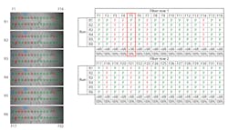
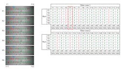
A simplified two-row MPO-16 auto-analysis repeatability test result is illustrated. Fiber 5 (indicated with the blue arrow) is an example of a marginal fiber endface, with the auto-analysis showing a passing assessment 50% of the time (three of six runs). All other fiber auto-analysis results are 100% consistent, indicating a high level of repeatability.
Ultimately, fundamentally due to the fact that the MPO/MTP cleaning tools hit all fibers on the multifiber endface without discrimination, it might be that only the top “connector” level pass/fail result is meaningful for scaleout network technicians to report. Documenting the individual fiber auto-analysis results may not be cost effective in terms of opex or ultimately informative to operators themselves in the fastest moving information technology enterprise. So it is connector-level repeatability, it seems, that needs to be the center of gravity for informed data center managers.
Cost sensitivities
As mentioned earlier, fast wireless MPO inspection microscope designs leverage smartphone semiconductor economics and capability. The current generation of these probes use 5- or 10-Mpixel CMOS image sensor chips, for example. Given 10-micron (or so) fiber core diameter dimensions, one can pretty quickly understand that pixels are at a bit of a premium. As higher-density image sensors are developed and cost-reduced for the billion-unit smartphone makers, these video microscopes will continue to improve.
The same can be said with respect to microprocessor MIPS (millions of instructions per second, a common performance metric) and memory density. All will continue to improve thanks to Moore’s Law, even as this unnatural law slows down below 10 nanometer minimum feature sizes. The most advanced inspection microscopes today use liquid lens optics to enable innovative form factor industrial designs, and these optics will continue to improve and decrease in price, if past trends predict the future.
In conclusion, fast MPO/MTP connector inspection probes are here to stay. AFL’s own FOCIS Lighting (pictured) is a good representative of this new class of multifiber inspection probes. These tools offer impressive levels of pass/fail auto-analysis performance, within the limits of semiconductors, optics, physics and cost. They will become more capable with time, and introduce “computational photography” innovations now common in smartphones—high dynamic range images, wider fields of view, 3D surface focus techniques, etc. Nowhere is the science-fiction trope of faster machines building faster machines more evident than in modern optical communications networks, and the test and inspection tools that enable them to hum.
Maury Wood is senior product line manager with AFL.


