NVP's role in field-testing twisted-pair cabling insertion loss
Insertion loss is defined differently in TIA specs than it is in ISO specs.
By Igor G. Smirnov, Signamax; and Robert Y. Faber, Siemon
Despite the fact that telecommunications standards groups such as the International Organization for Standardization/International Electrotechnical Commission (ISO/IEC; www.iso.org/www.iec.ch) and the Telecommunications Industry Association (TIA; www.tiaonline.org) have “harmonized” virtually all transmission performance requirements, there is still one balanced twisted-pair transmission parameter that is defined differently and tested differently per the ISO/IEC and TIA requirements. This parameter is insertion loss (IL), also known as attenuation.
This article will address the Category 6 (ANSI/TIA) and corresponding Class E (ISO/IEC) cabling field-testing criteria, as it relates to installations of new cabling systems. Coincidentally, everything offered in this article may be applied to cabling systems of other categories/classes with appropriate adjustments to the corresponding formulae.
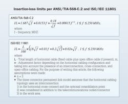
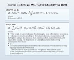
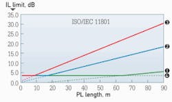
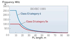
The fundamental difference between TIA and IEC specifications and IL-limit calculation methods lies in how the two standards define the maximum allowed length of the permanent link. These definitions are detailed in the figure below.
An additional condition is defined in ISO/IEC 11801: Insertion loss at all frequencies that correspond to calculated values of less than 4.0 dB shall revert to a maximum requirement of 4.0 dB.
Although this note may appear to be insignificant, in fact this approach significantly alters the field-testing criteria and may lead to some misunderstanding among those who are unaware of its implications.
When field testing to the ANSI/TIA-568-C.2 specifications, the field tester should use the standard constant limit for each frequency test point (per ANSI/TIA-1152 requirements for testing procedures and field-tester accuracy) within the frequency range of interest, without any reference to the length of the permanent link under test. On the other hand, when testing to the ISO/IEC 11801 specifications, it is absolutely necessary for the field tester to acquire the actual length value of the permanent link under test in order to calculate the corresponding IL limit.
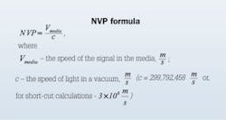
The only length of the object under test that is available to the field tester is the length it can measure. Because the tester can manipulate electrical transmission parameters only, the length can be measured based on the round-trip time (i.e., delay) of the signal launched by the tester into the transmission line. In order to calculate the distance (i.e., length of the link) the signal travels, the tester should know the propagation time (also known as propagation delay or PD, measured in nanoseconds) and the speed of the signal propagation in the given transmission media. The measurement method used to characterize PD is known as the nominal velocity of propagation (NVP), which characterizes the speed of the signal in the balanced twisted-pair media relative to the speed of light in a vacuum.
NVP is a dimensionless parameter, usually expressed in two forms—decimal fraction (e.g., 0.72) or percentage (e.g., 72%). Because the speed of light in a vacuum is the highest speed that can be achieved by an object of any nature, NVP values are always below 1 or 100%, with values typical to common balanced twisted-pair cabling lying in the 0.6 to 0.8 (or 60% to 80%) range.
Therefore, in order for the field tester to test permanent-link IL to the ISO/IEC 11801 specifications, it must have the accurate NVP setting. An inaccurate NVP setting will result in inaccurate IL measurement results.
In order to obtain experimental data, which may be used for illustrative purposes in this article, two lengths—30 meters (100 feet) and 90 meters (295 feet)—of Category 6 U/UTP cable were used and tested for IL and length using corresponding specifications of ANSI/TIA-568-C.2 and ISO/IEC 11801 as part of the field tester’s firmware. During the experiments, we measured IL and length in relation to the changes in NVP. The field tester that we used in these experiments is capable of adjusting NVP in the range between 0.50 and 0.99 (50% and 99%).
Experimental data demonstrates there is no difference between length testing per the ANSI/TIA-568-C.2 and ISO/IEC 11801 specifications. In addition, from the test-result graphics, the degree of error can be estimated in case the NVP has been set incorrectly. For example, for one particular cable under test, NVP deviation from its actual value of 0.5 may lead to the error in length testing of up to 2 to 3 meters (6 to 10 feet).
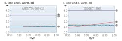
The graphics nearby offer an explanation of an actual example of the difference between testing per TIA and ISO requirements. When using the TIA approach, regardless of the length and NVP, the limit line is absolute for a given frequency. When using the ISO approach, the red line indicates what the limit would be if only the basic formula is used.
In conclusion, we can make three statements about NVP and the field-testing of balanced twisted-pair cabling systems for insertion loss.
1) The correct NVP setting is necessary when testing permanent-link length per both TIA and ISO/IEC specifications.
2) The correct NVP setting is necessary when testing permanent-link IL per ISO/IEC specifications. IL pass/fail criteria are directly related to field-tester length based on NVP accuracy.
3) The NVP value set in the field-tester memory does not influence IL testing per TIA specifications. Because calculations of the TIA IL limits do not involve NVP, accuracy of NVP setting cannot influence the resulting pass/fail criteria of IL testing.
Igor G. Smirnov, RCDD is product manager with Signamax Inc. (www.signamax.com). Robert Y. Faber, Jr. is global accounts manager for Siemon (www.siemon.com).

