The importance of measuring fiber loss and distances
A vendor's estimation is no substitute for an actual measurement.
Fiber optic networking can be a daunting undertaking, but it really is not as difficult as it seems. Understanding factors such as fiber modes, launch power, receive sensitivity, cable attenuation, and budgets will make your fiber networking installation projects run much smoother and more efficiently.
But even though vendors try to simplify the task of calculating maximum fiber distances and signal losses for you, the fact is we do not have all of the variables (fiber characteristics, number of splices, and other physical parameters) necessary to accurately provide such distance and loss specifications for a specific installation. The best any vendor can do is help you identify the variables and provide standard, industry-accepted quantities for those variables that can help you calculate the data (distances, budgets, etc.) you need. A vendor's estimation is no substitute for an actual measurement.
Know the terms
Before getting into actual fiber budget calculations, here are some commonly used terms that you'll need to know:
Launch power-Amplitude (or energy) of the light as it leaves the fiber transmitter. This energy level is usually measured in decibels relative to 1 mW (dBm).Receive sensitivity-Minimum energy required for the fiber receiver to detect an incoming signal (measured in decibels relative to 1 mW).Receive saturation-Defines the maximum power input before overdriving the receiver. Overdriving the receiver can create data errors or fail to detect any data at all (measured in decibels relative to 1 mW).Calculating loss, distance
From this point forward, all data transmitted over the fiber link is considered to be full-duplex (FDX). It cannot be overemphasized that in a half-duplex (HDX) environment, timing considerations limit the fiber link distances, and these limitations apply no matter what fiber you are using-singlemode or multimode.
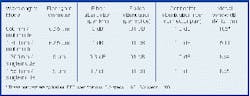
Since there are two distinct types of fiber cable, and three commonly used wavelengths-850 nm, 1,300 nm, and 1,550 nm-the attenuation measurement will vary depending upon which cable and wavelength is in use. Attenuation is measured in dB and is either quoted as attenuation in dB/km, or via an attenuation chart giving the attenuation for the entire fiber run. Note that the decibel scale is logarithmic-a loss of 99% of the light over a given length of fiber is expressed as -20dB.
Fiber loss variables include:
Attenuation-All fiber cabling has losses caused by absorption and back reflection of the light by impurities in the glass. Attenuation is a function of wavelength and needs to be specified or measured at the wavelength in use.Modal dispersion-The higher the data rate, the shorter the distance the signal can travel before modal dispersion creates an inability to accurately detect a "1" from a "0". Modal dispersion is only a concern with multimode cable and is directly proportional to the data rate.Dispersive losses-While singlemode fiber is not subject to modal dispersion, other dispersion effects cause pulse-spreading and limit distance as a function of data rate. Chief among these is chromatic dispersion, where the broader spectrum of certain transmitter types can result in varying travel times for different parts of a light pulse. Chromatic dispersion typically only starts to become a limiting factor at Gigabit speeds.Splices-Although small and often insignificant, there is no perfect loss-less splice. Many errors in loss calculations are made due to a failure to include splices. Average splice loss is usually less than 0.1 dB.Connectors-Like splices, there is no perfect loss-less connector. It is important to note that even the highest quality connectors can get dirty. Dirt and dust can completely obscure a fiber lightwave and create huge losses. A 0.5 dB loss per connector is commonly the worst-case scenario, assuming a cleaned and polished connector is used. There will always be a minimum of two connectors per fiber segment, so remember to multiply connector loss by two.Safety buffer-It is common to add a couple dB of loss as a design margin. Allowing for a 2 to 3 dB of loss can take into account such factors as fiber aging, poor splices, temperature, humidity, etc., and ensure a solid system.To determine minimum/maximum losses and maximum distances, you need to identify all of the above variables. Failure to identify even one of these variables can create potential problems.
The ideal method in determining losses is to actually measure the losses once the fiber has been laid. This, of course, will not be practical for initial fiber designs. But always test and validate your losses once the fiber is laid. (Note that all calculations assume FDX mode of operation.)
The numbers listed in the fiber loss table (page 22) are averages. Numbers for your installation may vary.
Calculating signal loss
There are commonly two different calculations required for fiber. Each assumes you have known values for different set of variables:
- One calculation determines the maximum signal loss across a piece of pre-existing fiber.
- The other calculation determines the maximum fiber distance given known budget and loss variables.
Calculating maximum signal loss is simply the sum of all worst case variables within your fiber segment. The numbers shown in the table are average losses. Your losses could be higher or lower depending upon many factors.
| Loss | = (Fiber attenuation x km) |
| + (Splice attenuation x # of splices) | |
| + (Connector attenuation x # of connectors) | |
| + (Safety margin) |
As an example, let's assume you want to know the average losses on a run of 10 km of 1,300 nm singlemode fiber with one splice. Let's include connector losses as well:
| Loss | = (0.3 dB x 10) | = 3 dB |
| + (0.1 dB/splice x 1) | = 0.1 dB | |
| + (0.75 dB/connector x 2) | = 1.5 dB | |
| + (3 dB safety) | = 3 dB | |
| = 7.6 dB total loss | ||
Calculating the signal strength exiting a cable is only half the job. To avoid overdriving a fiber receiver and eliminate data loss problems, it is equally important to calculate the maximum signal strength.
Overdriving a receiver is most common when using singlemode products with very low fiber attenuation. It is safe to assume average numbers for fiber loss, but you should measure the actual losses once the fiber has been laid, spliced, terminated, etc., to verify your previous measurements and avoid performance problems.

Calculating fiber distance includes not only the loss variables previously described, but requires the launch power and receive sensitivity specifications on your fiber products.
The equation can get a bit complicated, as many vendors provide a launch power range. Therefore, when calculating distance, you should use the lowest launch power to calculate a worst-case distance. The highest specified launch power should be used to verify you are not overdriving the receiver.
Distance is calculated first by calculating the power budget, found by subtracting the receive sensitivity from the launch power. Do yourself a favor and calculate the budget using both the minimum and maximum launch power specifications.
Budget and fiber distances
Assume you are connecting a fiber switch with a -17 dBm minimum launch power to a media converter with a worst-case receive sensitivity of 30 dBm:
| Power budget | = (-17 dBm) - (-30 dBm) |
| = 13 dB power budget |
You may be wondering why subtracting two numbers with dBm as the unit of measure results in a number with dB as the unit of measure. Remember, a dBm is a logarithmic ratio of power relative to 1 mW. Subtraction of two logarithmic ratios is the equivalent of dividing the two power measurements directly, resulting in a unitless number expressed in dB.
For example, if the equation is expressed in mW rather than dBm:
| Fiber budget | = .020 mW/.001 mW |
| = 50 |
This means the system can sustain a total loss of 98% of the transmitted light, or 1/50th of the transmitted light must reach the receiver. The use of dB and dBm as units allows addition and subtraction of reasonable-sized numbers rather than multiplication and division of very large or very small numbers.
For a given power budget, and making some assumptions about the number of splices and connections, you can also estimate the distance you can run a fiber of particular specifications. For example, using the numbers from earlier:
| Power budget | = | 13 dB |
| Losses from splices | = | -0.1 dB |
| Losses from connectors | = | -1.5 dB |
| Safety margin | = | -3 dB |
| Net power budget | = | 8.4 dB |
If the fiber is specified at a loss not to exceed 0.3 dB/km:
| (8.4 dB) / (0.3 dB/km) = 28 km |
You now have an idea of the distance you can safely run your piece of fiber before running out of signal strength at the receiving end.
Multimode cable tends to disperse a lightwave unevenly and can create a form of jitter as the data traverses the cable. This jitter tends to create data errors as the data rate increases. In addition to calculating budget across multimode fiber, you also need to calculate the losses resulting from modal dispersion. The maximum length of your fiber will be determined by distance calculation (above) or by modal dispersion-whichever is lowest.
For example, assume you are using 100 Mbits/sec Fast Ethernet (which has an actual bit rate of 125 Mbits/sec) across 850 nm multimode fiber. The modal dispersion of 850 nm multimode cable is 185 MHz-km. Use the following equation to calculate the maximum distance of a 125 Mbits/sec signal:
Similarly, calculating the maximum distance of a 10 Mbits/sec Ethernet data rate:
Seeing the light
Working with fiber is far less complex than it seems. Termination and splicing techniques, and the new small form factor connector and termination products have cut down significantly on the problems that once plagued fiber specialists. Within the next couple years, it is expected that the costs for integrating fiber will be at par with Cat 5 or above cabling. Companies are justifying fiber as a way to future-proof their networks. And companies such as IMC Networks are making it easier still by providing the products and the information to help you quickly and easily step into fiber networking.
Randy Bird is vice president of engineering for IMC Networks (www.imcnetworks.com), Foothill Ranch, CA.
Additional reference information
The following Web sites can provide you with more information on fiber networking:

