Testing high-performance cabling to standards and beyond
Is the practice of testing an installed high-performance cabling system an art or a science? There’s a strong case to be made that it’s a science; technicians must carry out test procedures exactly as prescribed, using properly calibrated machinery, to ensure accurate and useful results. However, those inclined to say testing is an art will point out that published industry standards do not prescribe every procedure for every installation. So even if it doesn’t necessarily take artistic flair to turn over a usable set of test results, it does take insight beyond what you’ll find in standards today.
Two presentations recently made during online seminars hosted by Cabling Installation & Maintenance illustrate these scenarios.
In a presentation titled “Fitting the Pieces Together: Test and Certification” on July 26, VIAVI Solutions’ product line manager Ed Gastle explained that several Telecommunications Industry Association (TIA) standards relate to fiber testing. He detailed the following.
- ANSI/TIA-568.3-D Optical Fiber Cabling and Component Standard—The “D” revision includes transmission performance and test requirements in Clause 7. Annex E, which is informative, provides guidelines for field testing. An addendum is being developed.
- ANSI/TIA-526-14-C-2015—This document, released in 2015, includes test procedures for installed multimode fiber cable plants. It is an adaption of IEC 61280-4-1 Ed. 2.0 and includes the encircled flux launch condition for 850-nm/50-micron fiber testing.
- ANSI/TIA-526-7-A—This standard defines test procedures for installed singlemode fiber cabling plants, and was released in 2015. It is an adoption of IEC 61280-4-2 Ed. 2.0
Both of the 526 standards are descendants of IEC 61280 standards, but one is an adaption and the other is an adoption. In brief, an adapted standard is reproduced from the original with some modifications. An adopted standard is reproduced without modification. Gastle explained that both TIA and ISO/IEC standards specify two tiers of certification for installed fiber systems. Tier 1 (or basic) incorporates loss, length, and polarity. Tier 2 (or extended) tests are optional additions to Tier 1 tests. Tier 2 testing is carried out using an optical time-domain reflectometer (OTDR), as opposed to Tier 1, for which a power meter and light source, or optical-loss test set, is required.
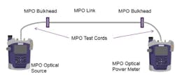
Tier 1 testing (setup illustrated below) provides a pass/fail result based on loss, length, and polarity. This testing method cannot ensure individual event losses (from splices and connections) are within specification. A Tier 1 test cannot ensure that cable attenuation is uniform. Tier 2 testing adds the characterization of these events to the certification test. Gastle further explained that Tier 2 testing is the ideal fiber troubleshooting tool; it is used to find the cause and location of excess loss, including breaks, and reflectance.
Gastle also discussed simplex or duplex fiber testing versus MPO testing. “Existing fiber test standards do not address MPO-specific concerns,” he pointed out. His presentation included the following statement: “Cabling testing standards such as IEC 61280-4-1 for multimode attenuation measurements and IEC 61280-4-2 for singlemode attenuation and optical return loss measurements describe testing simplex or duplex fiber cabling terminated with single-fiber ferrule connectors. These IEC standards are difficult to apply to the testing of installed multi-fiber cabling terminated with multi-fiber connectors (MPO).
The ISO/IEC’s Subcommittee 86C, Working Group 1 (SC 86C WG 1) released a technical report on testing MPO cabling in 2017. The document, IEC TR 61282-15:2017, “provides guidance for the testing of multi-fiber cable, multimode or singlemode, terminated with [MPO plugs],” the document’s abstract explains. “Guidance is provided on the measurement of attenuation, polarity, length and optical return loss.”
Gastle explained that the TIA’s TR-42.11 Optical Fiber Systems Subcommittee is working on an addendum to TIA-568.3-D. A current proposal within the group is for that addendum to reference the IEC technical report. Additionally, the IEC SC86C WG1 is working on an MPO-specific testing standard, which currently is in draft.
VIAVI’s Gastle also pointed to a practical reality for network and cabling managers, as well as technicians who work in data centers. In these facilities, many high-speed connections are made via active optical cables (AOC) or direct-attach copper (DAC) cabling. These fixed-length cables are terminated to QSFPx or to SFPx transceivers. In these applications, testing can be challenging.
“There is no test access to the actual fiber or copper cabling,” Gastle explained, because the media terminates directly to the transceiver. “Traditional media tests cannot be used to certify the cable,” he added. Technicians need a tester than can accept dual SFP/QSFP transceivers.
The primary parameter of an AOC/DAC cable is bit error rate (BER). BER testing can be accomplished using a stress pattern, such as PRBS 31 (Pseudo-Random Binary Sequence 31), Gastle explained. Pass/fail criteria can be determined by comparing PRBS 31 results to a cable BER specification.
To employ this test method, before the AOC/DAC is installed, the technician uses a single unit containing 2 ports; each end of the cable is inserted into one of the ports and the cable is evaluated before being installed. After the AOC/DAC is installed, the technician needs two test units, to access each end of the cable. Each end is connected to a test unit, a cable test script is run on the first unit, then monitor/through-mode (loopback) is run on the second unit.
In a seminar on July 10, Fluke Networks’ regional marketing engineer Jim Davis delivered “Requirements for Field Testing of Category 8 Systems.” In the presentation, he explained that Category 8 cabling systems, as specified in TIA-862-2.D, are intended for use in data centers, with permanent links up to 24 meters and channels up to 30 meters. Category 8 employs a 2-connector channel model, and direct attach or modular-plug terminated link (MPTL) constructions are allowed. Category 8 uses a backward-compatible RJ45 connector interface. Davis pointed out that another aspect of Category 8 that will be familiar to many users is the set of field tests it requires. The TIA-1152-A standard specifies Category 8 field testing and was published in late 2016. It references related standards such as TIA-568.C-2, specifies which tests shall (must) be run in the field and which tests are optional, describes how to run field tests for Category 8, and prescribes an accuracy requirement for field testers.
When explaining why it is best practice to certify installed links (of Category 8 or other cabling performance levels), Davis said that certification ensure the installed cabling meets the performance level that end-user organizations are paying for. Speaking of paying, for contractors, typically a set of passing test results is necessary before the end-user customer will issue payment for the installation job. Additionally, he said, experience has shown that a certified network runs faster. Errors known as cyclical redundancy check and frame check sequence errors lead to packet retransmissions, thereby slowing actual throughput.
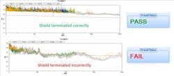
As Davis mentioned, many of the tests performed during Category 8 certification are familiar—including length, insertion loss, resistance, and crosstalk. What will be new to many is shield testing. Category 8 cable is fully shielded (S/FTP), and ensuring screen continuity is necessary. David explained, “Wiremap testers use DC resistance measurements to ensure the shield is correctly terminated and presented in a cabling system. In data centers, this can result in a false pass, and poor alien crosstalk.” Simply running a DC resistance test does not ensure shield continuity, he pointed out.
To perform compliant Category 8 testing, a test instrument must achieve Level 2G accuracy as defined in TIA-1152-A. That standard reads in part, “For Level 2G testers it is understood that the screen continuity is tested along the path of the cabling.”
While shield continuity testing is required in 1152-A, DC loop resistance and DC resistance unbalance measurements are not. Performance limits for those electrical characteristics are specified, but testing those characteristics is optional.
A cabling channel’s DC resistance and DC resistance unbalance performance affects its ability to support direct-current (DC) power via technologies like IEEE-specified 802.3af, 802.3at, and particularly 802.3bt Power over Ethernet. Fluke Networks has emphasized the importance of ensuring a system’s DC resistance and resistance unbalance performance, recently posting in its blog, “Excessive DC resistance unbalance between multiple pairs can wreak havoc on data transmission and cause PoE to stop working.”


