Physical layer architectures for enterprise networks
By Patrick McLaughlin
When the concept of a structured cabling system emerged and took hold in corporate environment, user needs in enterprise networks were fairly straightforward. A wired voice line and wired data line to each desk connected each worker to the outside world as well as to internal network devices and applications such as email, intranets, and printers. To be prepared for future needs, some organizations specified one or two spare connections to each desk. Typically, most workers resided in open-office (cubicle) workspaces. Some resided in hard-walled offices, so the cabling-system design had to accommodate for these different physical workspaces.
Wireless networks theoretically operated in the range of double-digit Megabits/sec. But that’s shared throughput, so the handful of workers in an enterprise who had mobile work devices (e.g. laptop computers) shared that data rate when they gathered in a conference room that contained an access point.
Now that we have taken a trip down decades-old memory lane, we can compare and contrast characteristics of worker needs then with worker needs now. In many cases, the buildings and campuses have not changed much—drop ceilings, cubicles (albeit with different wall heights perhaps), conference rooms, walled offices for executives—but user requirements have changed significantly.
New generation
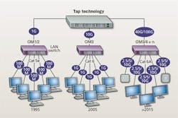
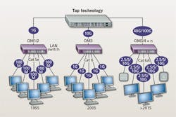
On one hand, speeds have increased. The scenario described earlier likely had 10-Mbit/sec data connections to the desktop initially, with 100-Mbit/sec network backbone speeds. When 100 Mbits/sec to the desk became practical and common, backbones had to accommodate by increasing to 1 Gbit/sec. For many organizations, the advent of the 1-Gbit/sec backbone also meant deploying fiber-optic cabling to support it. Today, some of those organizations have increased tenfold again, with 1-Gbit/sec connections to the desk and 10-Gbit/sec backbones. Wireless LANs have experienced multiple generations of advancement, to the point at which the (theoretical, shared) throughput capability today is multi-gigabits.
In addition to speed increases, modern networks are more demanding than earlier generations in that the number of applications requiring network support has increased. Some of these applications are user-based; some are not. For example, it used to be that only power users (and/or power holders) were issued laptop computers requiring wireless network access. Today, a laptop is essentially a commodity network device, issued to every worker and ignored by the many who access the network only from other mobile devices. Wireless access points may not be everywhere in an enterprise network, but wireless access for users is everywhere—and it has to be, because users from all over the building require access from every corner of it. Site surveys and wireless-signal verification are common practices that ensure wireless connectivity throughout a workplace.
The extension of service providers’ cellular wireless networks into the enterprise has brought dramatic change to the planning, design, installation and management of enterprise networks. Once predominantly the domain of high-profile gathering spots like stadiums and arenas, the on-premises distributed antenna system (DAS) is becoming a practical necessity for many organizations whose users’ personal mobile devices are business tools requiring ubiquitous connectivity.
Wireless connectivity, then, is a user-based application that has evolved and become more demanding over time. It has gone from an application used by few to an application used by many, requiring more and better infrastructure in the process. Voice is another, in that few enterprises employ plain old telephone service (POTS) voice systems. Internet Protocol (IP) voice is now widespread.
In the span of time in which that happened, other applications that are not employed by each user became network-based. IP-based surveillance is a widespread example. While IP surveillance may or may not be “owned” by a company’s information technology department, it requires capable network infrastructure, including cabling, to operate successfully.
The network application du jour is lighting. Currently, intelligent lighting systems that employ Power over Ethernet remote powering represent an initial step into the realm of intelligent buildings. Some of these advanced systems incorporate sensors that collect and share information about lighting use. Installers and users of systems that have been employed to date report energy-efficiency gains. These connected lighting systems, and any other sensor-based building systems that collect and share use data, are other examples of network applications that must be planned for and supported in enterprise environments.
Examining topologies
Designers, installers, and administrators of cabling and wireless systems used in today’s enterprise environments have far more to consider, and far greater demands to meet, than was the case when horizontal data-transmission speeds were 100 Mbits/sec. As such, the performance levels of cabling components and systems, as well as the physical structure of those systems, has evolved accordingly.
In a white paper titled “Fiber backbone cabling in buildings,” CommScope emphasizes the importance of deploying high-performance, highly capable optical fiber. The company explains, “Backbone cabling provides interconnections between access provider space, entrance facilities, equipment rooms, telecommunication rooms, and telecommunication enclosures. ANSI/TIA-568.3-D recommends deploying a hierarchical star topology for the backbone, with no more than two levels of crossconnections. For the simplest design, the main crossconnect in the equipment room feeds directly to the horizontal crossconnect in the telecommunication room on each floor. Optional intermediate crossconnects may be positioned between the main crossconnect and horizontal crossconnect.”
Concerning fiber types, CommScope adds, “The standard recognized transmission media for backbone cabling comprise multimode and singlemode fiber. Laser-optimized 50/125-µm (Om3 and Om4) multimode fiber is recommended and is typically installed for 10-Gbit/sec building backbones up to 300 meters and 550 meters, respectively … Singlemode fiber is typically installed where the channel lengths are expected to exceed the capabilities of multimode fiber—when exceeding the Om4 support distance for 550 meters for 10 Gbits/sec.
“With continued growth in data rates in the horizontal driven by applications such as 802.11ac and in-building wireless, the backbone should be designed to accommodate speeds of 40 Gbits/sec or 100 Gbit/sec,” CommScope concludes. “Planning for a seamless migration path ensures that the backbone will be able to support high-capacity wireless and other high-bandwidth applications that may emerge.”
Optical options
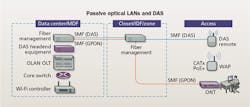
In recent years the technology commonly called passive optical LAN has emerged as an enterprise network technology whose architecture differs from the hierarchical star recommended in TIA-568.3-D. Passive optical LAN, or simply optical LAN as it also is frequently called, is based on Gigabit Passive Optical Network (GPON) and/or Ethernet Passive Optical Network (EPON) point-to-multipoint architectures.
An industry group called the Association for Passive Optical LAN has advanced and advocated passive optical LAN deployment since the association’s founding in 2013. In its white paper titled “How Passive Optical LANs are enlightening the enterprise LAN,” the association describes the point-to-multipoint architecture and several of its benefits. “In a traditional active Ethernet LAN, a router in the topmost layer (core layer) links to the campus or building aggregation switches (distribution layer) below. The distribution switches connect down to the access layer switches in the communications closets. Copper cables extend from the communication closets to the users.
“In a passive optical LAN solution, the router is retained in the topmost layer and the optical line terminal serves the same purpose as the campus aggregation switches,” the association continues. “The building aggregation switching is accomplished by the 1x32 (or 2x32 for equipment redundancy and fiber-route diversity) optical splitter, which is a passive device so there are no power requirements and little management while being highly reliable. The optical network terminals provide connectivity to the users and end devices.”
Recently, the Association for Passive Optical LAN’s marketing committee chair, John Hoover, authored an article on IOTInnovator.com titled “Passive Optical LAN: The perfect partner for the Internet of Things.” In that article he said, “The key characteristic that distinguishes POL from any alternative is its centralized architecture, intelligence and management. Essentially, POL works as one big switch with no other switches needed in between it and a vast number of end points. This means that to control a broad array of IoT products, as well as other corporate IT needs, often requires just one data center. With POL’s streamlined design, there is a reduction in space required as there are fewer telecom rooms, less cable mass and smaller and limited pathways required.”
In its “enlightening” white paper, the association explains synergies between passive optical LANs and DAS. “To be clear, the DAS traffic does not traverse the passive optical LAN equipment, but it can leverage the same fiber infrastructure that passive optical LAN utilizes,” the paper emphasizes. “Alone, DAS has a challenging return-on-investment analysis—it is relatively expensive, it only does one thing and the end customers think they should not have to pay for it. Passive optical LAN has an excellent ROI that can justify the deployment of DAS over existing spare fibers. In the near term, DAS and passive optical LAN can gain additional synergies with combined powering, power backup and fiber management between them. In the future, as both DAS and passive optical LAN technologies advance, it can be expected that the passive optical LAN ONT can integrate both DAS and WiFi access point hardware.”
Zoning in
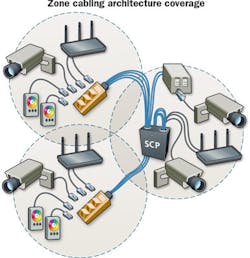
In the paper “Zone cabling and coverage area planning,” Siemon’s global sales engineer Valerie Maguire explains, “Zone cabling is ideal for supporting convergence of data and voice networks, wireless device uplink connections, and a wide range of sensors, control panels, and detectors for lighting, security, and other building communications. A zone cabling design consists of horizontal cables run from the floor distributor in the telecommunications room to an intermediate connection point that is typically housed in a zone enclosure located in the ceiling space, on the wall, or below an access floor. The name of this intermediate connection point depends on the types of endpoint device connection it serves, and on the applicable regional structured cabling standard. Connections at the service connection point are typically facilitated by connecting hardware supporting 2 to 96 outlets. Cables can then be connected from outlets in the service connection point to building devices, service outlets, or telecommunications outlets.”
The comprehensive document takes a detailed look at zone cabling designs and the applications they can support. It notes, “Zone cabling is a highly flexible infrastructure that is ideally suited for the convergence of voice, data, wireless, and building device applications over one managed network. Furthermore, outlets serving voice/data, wireless, and building device connections can be conveniently combined within one service connection point.”
The proclaimed arrival of the Internet of Things is requiring many enterprise networks to support more applications and more information transfer than ever—and certainly more than they did years ago. Not only the type and performance level of cabling, but also the architecture of the network’s physical layer, can play a role in the network’s ability to meet these new requirements.
Patrick McLaughlin is our chief editor.

