High-Density Fiber Connectivity Manifests in Smaller Interfaces, More Cores
Key Highlights
- VSFF connectors reduce the space occupied by individual optical interfaces, while multicore fiber increases the number of optical paths within a fiber.
- MPO trunks and VSFF duplex connections can complement one another in a data-center cabling architecture.
- High port density must be balanced with access for patching, inspection, cleaning, testing, and future changes.
- Multicore fiber requires precise core alignment and may use factory-prepared fanouts or specialized direct-connectorization processes.
- Common specifications, compatible test equipment, and approved installation procedures will support reliable deployment.
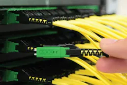
As artificial intelligence, high-performance computing, and cloud services drive the expansion of data-center infrastructure, the demand for optical connectivity continues to grow. Network designers are challenged to accommodate increasing numbers of fiber connections without allowing patching fields, cable pathways, and equipment racks to become unmanageably crowded.
Two developments offer help to system designers facing these tasks. Very small form factor (VSFF) connectors reduce the physical footprint of individual optical interfaces, allowing more connections in a given space. Multicore fiber (MCF) places multiple cores within an optical fiber, increasing the number of independent optical paths that can be accommodated within a cable of a given size.
These technologies are complementary, but they solve different problems. VSFF connectors primarily address the space occupied by connections and the hardware that accommodates them. Multicore fiber changes the construction of the optical transmission medium itself.
Both also raise new issues for cabling professionals who handle, install, and test fiber-optic systems. This article examines some technological developments and practical implications related to high-density fiber connectivity.
VSFFs Fitting More Connections in Less Space
Traditional duplex LC connectors have long provided a practical balance between compact dimensions, optical performance, and ease of handling. However, the continued expansion of high-speed optical networks has increased the pressure on the physical interfaces connecting transceivers, patch panels, and structured cabling systems.
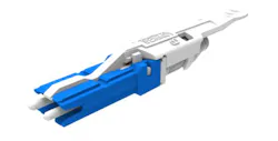
VSFF connectors address this pressure by reducing the space occupied by an optical connection. Several connector families exist including the CS, SN and MDC duplex connectors along with the SN-MT and MMC array connectors. Their designs differ, and they are not interchangeable, but they share the objective of accommodating more duplex connections within a limited footprint.
Greater density can reduce the rack space required for a given number of connections and help designers accommodate the interconnects associated with high-speed transceivers. Depending on the architecture, it can also facilitate fiber breakout close to the equipment rather than requiring all connections to remain in a centralized patching arrangement. The most-dense of these connectors can triple the density of fiber connections within a rack unit (RU).
VSFF and MPO: Two approaches to density
To understand the significance of VSFF connectors, it helps to compare them with the multifiber push-on (MPO) connectivity that has become widely used in structured data-center cabling.
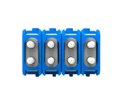
MPO connectors use a rectangular multifiber ferrule to align multiple fibers simultaneously. Common configurations accommodate 12 or 24 fibers, and 16- and 32-fiber MPOs are also available. Because a single connector can carry multiple optical channels, MPO systems are well suited to factory-terminated trunk cabling, structured cabling backbones, and parallel-optics applications.
VSFF duplex connectors take a different approach. Rather than placing many fibers within one rectangular ferrule, they package pairs of fibers into small individual connectors. This makes them particularly useful where a large number of duplex connections must be accommodated close to switches, servers, or optical transceivers.
The distinction is important because connector density is not the same as fiber density throughout an entire cabling system.
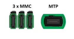
An MPO trunk can carry many fibers through a relatively small cable and terminate at a cassette or breakout assembly. The individual duplex connections beyond that point may occupy substantially more panel space. A VSFF design can reduce the space consumed by those individual connections, but the upstream cabling architecture still determines how fibers are aggregated and distributed.
Consequently, the two technologies should not be viewed as mutually exclusive. A data center might use MPO-terminated trunk cabling for efficient distribution between locations and VSFF connections near equipment where port density is especially important.
Limits of packing more ports into a rack
A panel's nominal port count is only one measure of its practicality.
At extremely high densities, technicians must work around closely spaced connector housings, release mechanisms, patch cords, and cable bundles. Connecting or disconnecting one port without disturbing adjacent connections becomes an important consideration. Cable bends, routing paths, labeling, and the ability to reach individual ports all influence how easily the installation can be maintained.
The compactness that makes VSFF attractive can therefore complicate hands-on work. An installer may be able to populate a panel with hundreds of fibers, but the resulting arrangement must still allow technicians to identify connections, manipulate latches, inspect end faces, clean connectors, and replace patch cords.
These concerns become particularly significant in data centers where frequent changes are expected. A high-density design that is difficult to service can increase the time required for moves, adds, and changes, potentially offsetting some of the space savings.
Designers should therefore consider connector accessibility and cable management when selecting VSFF hardware.
Testing VSFF connectivity: Adapting field tools to smaller interfaces
The growing availability of VSFF connectivity has prompted test-equipment manufacturers to develop compatible interfaces and procedures. For example, Fluke Networks’ CertiFiber Pro is available with MDC adapters and test reference cords, while CertiFiber Max is available with 16- and 24-fiber MMC adapters and test reference cords. These setups allow testing with a 1-jumper reference.
The company explains, “Testing CS and SN VSFF connectors on patch cords or installed cabling may require the 3-jumper method, using breakout test reference cords on either side of the cabling under test. Testing multifiber SN-MT connectors also requires the 3-jumper method, using a Y breakout cable with a 16- or 24-fiber VSFF connector on one end and two 8- or 12-fiber MPOs on the other, depending on the connector variant.”
Viavi Solutions offers the SmartClass Fiber OLTS-85/85P VSFF that natively supports VSFF connectivity. The company says, “The OLTS power meter port connects directly with the same plug/connector as the cabling under test to ensure a 1-cord reference method and to avoid the user of adaptive/extra test cords. VSFF connectors such as CS, SN, and MDC play a crucial role in hyperscale data center environments due to their space-efficiency, scalability, and performance. Fiber links and channels terminated with these connectors meet critical loss budget and latency requirements. The need for the right test tool becomes imperative to prevent optical loss, minimize reflections, and ensure that measurements are consistent and standardized according to industry best practices.”
Multicore Fiber: Increasing the number of optical paths
VSFF connectors reduce the footprint of the interface. Multicore fiber takes a different approach by increasing the number of optical paths within the fiber itself.
Conventional singlemode optical fiber has one light-guiding core surrounded by cladding, typically with a nominal diameter of 125 micrometers. Multicore fiber incorporates two or more light-guiding cores within a common cladding. Each core can carry an independent optical signal, allowing multiple spatial channels to share one physical fiber.
This approach is an example of space-division multiplexing (SDM). Rather than relying exclusively on additional fibers or additional wavelengths to increase capacity, SDM uses separate spatial paths to carry signals.
The potential benefits are significant in environments where the number of optical links is growing faster than the available space for cables, pathways, and connections. Multicore fiber can reduce the number of individual fibers required to provide a given number of optical paths. Depending on the system design, it may also reduce cable bulk and the number of physical connections that must be accommodated.
However, multicore fiber does not automatically multiply the throughput of every optical link by the number of cores. The transceivers, optical interfaces, transmission system, and network architecture must support the cores as independent channels. The resulting performance depends on the complete system, not just the fiber.
SDM4 MCF MSA and a common technical foundation
An important recent development is the publication of the SDM4 Multicore Fiber MSA Technical Specifications, Version 1.0, announced on September 17, 2026. The specification establishes common geometric, optical, mechanical, and measurement requirements for a four-core multicore fiber intended for short-reach applications, including AI data centers and campus networks.
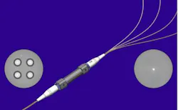
The specification defines a four-core arrangement in which the cores form a square lattice, with a nominal core-to-core pitch of 40 ± 1 micrometers. The fiber has a nominal cladding diameter of 125 micrometers, comparable to that of conventional single-core fiber. It also specifies optical characteristics for O-band applications and limits crosstalk between adjacent and diagonal core pairs to −40 dB or less at 1 kilometer and 1310 nanometers.
The four-core configuration provides a useful illustration of the density opportunity. Four optical channels can occupy a fiber with approximately the same outer cladding diameter as a conventional single-core fiber.
That does not mean a completed four-core cabling system will necessarily occupy one-quarter the space of an equivalent conventional system. Cable construction, strength members, protective jackets, connector hardware, fan-out assemblies, and installation requirements all contribute to the final dimensions. Nevertheless, increasing the number of optical paths per fiber can substantially improve the efficiency with which physical cabling infrastructure is used.
The MSA's significance also extends beyond its geometry. A common specification gives manufacturers a shared technical foundation on which to develop compatible products.
For cabling professionals, the specification is therefore worth watching not only as a description of a new fiber design but also as a sign of progress toward a more consistent multicore-fiber marketplace.
The practicalities of termination and connecting
The density advantages of multicore fiber introduce a challenge for installers: how to connect each core to its appropriate optical channel while maintaining alignment and performance.
With conventional single-core fiber, the core is aligned within a ferrule or fusion splice using established manufacturing and installation processes. With multicore fiber, the technician must account for the positions of multiple cores within the same cladding. Their locations and orientation relative to the fiber's exterior become important.
This distinction affects both splicing and connectorization.
Approach 1: Factory-prepared fanouts
One established approach to accessing individual cores is a fanout assembly.
A fanout converts the multiple cores in one multicore fiber into separate conventional single-core fibers. Those individual fibers can then be connected to familiar optical interfaces or spliced to other single-core fibers.
In one manufacturing approach, a bundle of single-core fibers is arranged and tapered until the spacing between their cores matches the geometry of the multicore fiber. The resulting fused structure is cleaved and spliced to the multicore fiber, creating a transition between its individual cores and separate optical fibers.
For an installer, the important distinction is that this process is not equivalent to terminating four ordinary fibers independently.
The geometry must be carefully controlled so that every core in the multicore fiber couples to its intended output. The alignment requirements are sufficiently demanding that the specialized fanout assembly is prepared using controlled manufacturing processes rather than improvised at the jobsite.
A practical installation can therefore use factory-prepared multicore cable assemblies with fanouts at their ends. The installer routes and secures the cable, protects the transitions, connects the conventional fiber outputs, and performs the required testing.
This approach reduces the amount of specialized work required in the field. It also provides a relatively familiar interface for technicians who already work with conventional single-core fiber.
Fanouts occupy space and introduce a transition assembly that must be accommodated in enclosures or patching hardware. Designers must account for that transition when evaluating the overall space savings of multicore fiber.
Approach 2: Direct multicore-fiber connectorization
A second approach is to terminate the multicore fiber with a connector designed to preserve access to its multiple cores.
This is more demanding than using a conventional connector on a single-core fiber. The connector must align the entire multicore geometry with the corresponding optical interface. Rotational orientation matters because turning the fiber can change the positions of all its cores relative to the mating component.
For example, a four-core fiber with a square arrangement has four distinct core positions. The connector must orient that arrangement correctly so that each core couples to the intended channel in the mating interface. Even if the fiber's outside diameter and cladding are within specification, an incorrect rotational alignment can produce unacceptable optical loss or incorrect channel mapping.
Connector manufacturers are developing processes and hardware to address this challenge. A May 2026 technical note from Senko discusses multicore-fiber connectorization and the need for precise rotational alignment. It describes development work aimed at automating termination of multicore fiber using standard connector types, with a target alignment precision better than one degree. This is a development target, not a universal requirement or proof that every standard connector can already terminate multicore fiber.
For installers, the central lesson is that a conventional connector's physical compatibility with a cable does not establish its optical compatibility with the cable's internal core arrangement.
A connectorization process must account for the specific fiber geometry, connector design, rotational orientation, and applicable optical-performance requirements. The procedure also must preserve the fiber's mechanical integrity while avoiding damage to the cores or cladding.
Until such processes are broadly established for the intended application, installers should follow the fiber and connector manufacturers' approved procedures rather than treating multicore fiber as an ordinary single-core fiber with an unusual appearance.
What VSFF and MCF mean for cabling pros
VSFF connectors and multicore fiber offer two different ways to address the growing physical demands of optical networks. Their value depends on how well they are integrated into the complete cabling system.
For designers, the first priority is to identify where density is actually constrained. If the primary limitation is the space occupied by duplex ports at equipment interfaces, VSFF connectors may offer an immediate benefit. If the challenge is the number of individual fibers that must be routed through pathways or between locations, multicore fiber may provide a more fundamental improvement.
For installers, the priority is to understand what can be handled using familiar methods and what requires specialized processes. VSFF connectors retain familiar single-fiber optical interfaces in smaller housings, but their compact dimensions demand suitable management and testing procedures. Multicore fiber introduces a more substantial change because its internal geometry affects how optical channels are accessed and aligned.
For network operators, maintainability deserves particular attention. A high-density installation must remain accessible for troubleshooting, replacement, and future expansion. Connector family, component availability, test-equipment compatibility, documentation, and technician training all influence the long-term value of the design.
Density must be practical, not just theoretical
The evolution of high-density fiber connectivity is moving on two fronts. VSFF connectors are reducing the space occupied by individual optical interfaces, while multicore fiber is increasing the number of optical paths carried within a single fiber.
Both developments can help data centers accommodate the demands of AI, high-performance computing, and increasingly interconnected infrastructure. Neither, however, eliminates the need for careful engineering.
The most successful installations will balance nominal density with accessibility, reliable optical performance, component availability, and the ability to test and maintain the completed system. For multicore fiber in particular, the industry's progress toward common specifications and repeatable connectorization methods will help determine how quickly the technology moves from specialized applications into broader deployment.
For cabling professionals, the opportunity is substantial, but so is the need to understand the practical details. The next generation of high-density fiber networks will depend not simply on fitting more optical channels into less space, but on making those channels dependable and serviceable throughout the life of the network.